Grid Manager
Projects > Coordinate System > Grid Manager

Define and manage additional grids for the project. Additional grids can be used for creating construction in views, and for showing them on drawings.
Note: In COS projects, the general project data (Hull project general) must be checked out when defining new grids or making changes to existing grids.
See also Defining grids in reference planes in the Modeling Construction Items User's Guide.
The following types of grids can be defined: length grids, width grids, height grids and arbitrary (slanted) grids. These grids can only be modified in the System Management and HiLTop applications.
The frame coordinate list that is inherited from the shape database cannot be modified. An alternative length grid can be defined, and then be set as the default length grid for the block. Setting the grid as the default grid is done in System Management > Projects > Building Block Overview.
Viewing and editing grids
The properties and grid point details of each defined grid can be checked and edited in the Grid Manager main dialog which opens when Grid Manager is started.
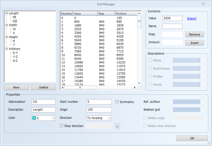
The grid tree on the left shows all the grids defined for the project. The tree is fully expanded when Grid Manager opens. Select a grid to see the grid's properties and grid point details.
When editing the fields press Enter to apply a change.
To delete a grid, select it and click Delete.
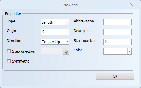
To define a new grid, click New. This will open the New grid dialog where you define the grid. See Defining a new grid for detailed information.
Grid Properties
The selected grid's properties are shown below the grid tree in the Properties section where the properties can also be edited. The properties are as follows:
-
Abbreviation – The name of the grid, shown also as a prefix for the grid points (grid values).
-
Description – The description of the grid. The description is shown in selection lists of available grids.
-
Color – Sets the color of the grid when it is shown in the graphical window.
-
Start number – The first grid point's value. The start number can only be entered for non-symmetric grids. For symmetric grids the value is automatically set to 0 and cannot be changed.
When Symmetric is selected, the grid is mirrored over the grid's starting point into the opposite direction of the grid's defined direction.
-
Origin – The starting (origin) point of the grid.
-
For length, width and height grids, the origin is defined as a value in mm.
-
For arbitrary grids, the origin is defined as point coordinates. Enter the coordinates, or click the current control button
 to use the coordinates of current control position. You can use Snap keys to change the current control position in the graphical window while keeping the dialog open.
-
-
Direction – The direction in which the grid runs.
-
For length, width and height grids, the direction is defined as To foreship (default) or To aftship for length; To starboard (default) or To portside for width; To top (default) or To bottom for height.
-
For arbitrary grids, the direction is defined as vector coordinates. Enter the coordinates, or click the mouse pointer button
 to indicate a line in the graphical window. The direction of the line will be used as the grid direction.
-
-
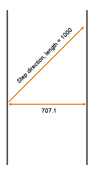
Step direction –Sets the direction along which the step length should be measured. For example, in a width grid with a step of 1000 and a step direction of (0,1,1), the resulting distance between two consecutive grid lines will be 707.1.
-
Ref. surface – Defines the reference surface onto which the grid is placed. This can be defined in the HiLTop application only. The following requirements must be met or the drop-down list will not be available:
-
The grid must be an arbitrary grid.
-
The reference surface must be present in the hull database.
-
The view containing the virtual plate of the reference surface must be open in the background.
-
-
Related grid – Sets a another grid to be related to the currently selected grid. Only grids attached to reference surfaces can be related to each other. Select the grid to be related from the drop-down menu.
-
Relate origin – Sets a grid line of another grid to be related to the origin of the currently selected grid. The grids must be attached to a reference surfaces. When selected, the first grid line of the currently selected grid and the specified grid line of the other grid will intersect.
-
Relate step direction – When selected, also other grid lines of a related grid than the one selected in Relate origin will intersect with the grid lines of the currently selected grid. The grids must be attached to a reference surfaces. The step direction for the currently selected grid is calculated so that the same step direction for both the current grid and the related grid will result in intersecting grid lines along the intersection line of the respective reference surfaces.
Grid point details
The selected grid's grid point details are shown in the table in the middle of the dialog. The table shows each grid point's number (grid value) on a separate line. Select a line to see that grid number's details. The grid point details are shown in the columns in the table, and for some also on the right side of the dialog in the fields of the Contents and Descriptions sections where they can be edited.
The columns and fields are as follows:
-
Number – The grid point number, representing a grid value. The first number is defined in Start number.
-
Value – The distance of the grid point in millimeters measured from the grid's origin point. The starting (origin) point is defined in Origin in the Properties area.
-
Step – The distance between grid points in millimeters. The step size can be defined between two or more grid points. You can select multiple grid points by pressing Ctrl or Shift when selecting grid points in the list. When no grid values have been defined yet, determines the step size between all grid values that will be created.
-
Position – The actual position of the grid point in the drawing in millimeters (as opposed to the distance from the origin which is defined as Value). For arbitrary grids, the value and position columns are the same.
-
Name – An alternative name for the grid point.
-
Amount – When no grid values have been defined yet, this determines the maximum amount of grid values. When modifying a grid, determines the number of grid values to be added to the already existing ones. To be able to edit this field you must select the grid in the grid tree (not individual grid point).
-
Descriptions – Adds an alternative, user-defined description to a grid value for construction parts with a fixed length: plates, shell frames, profiles and panels. If a description has been defined, it will override any description defined in the Logistics > Description menu defined in the System Management application.
The drop-down list contains alternative predefined descriptions that can be selected. Descriptions can contain keywords that are replaced automatically. These descriptions are added and modified in System Management > Logistics > Description > Alternatives. Doing so also affect the description(s) assigned to any grid values. See Description in the Managing Production Information Administrator's Guide.
Functions in the Contents section
The following functions are available in the Contents section of the Grid Manager dialog.
- For the Value field: Import or Update.
Import – Imports a text file containing a grid definition. This function can be used when creating a new grid or editing an existing grid. The text file must be formatted so that the first value is the line Number of the grid, and the second value is the Value. The values must be separated by a space. For example:
1 5002 10003 16424 2284The file extension of the text file depends on the grid type:
.FCL for a length grid
.TXT for a width grid
.TXT for a height grid
Update – Updates the frame coordinate list. Applicable only to the main length grid.
- For the Step field: Remove – Removes the selected value(s) from the grid points list.
- For the Amount field: Insert – Inserts the newly defined values into the points list of the selected grid.
Defining a new grid
Do the following:
-
Click New below the grid tree. The New grid dialog opens.
-
Select the type of the grid in Type.
-
Set the starting point of the grid in Origin.
-
For length, width and height grids, enter the value in mm.
-
For arbitrary grids, enter the coordinates, or click the current control button
to set the current control position as the origin. You can use Snap keys to change the current control position in the graphical window while keeping the dialog open.
-
-
Set the direction of the grid in Direction. This is the direction in which the grid runs.
-
For length, width and height grids, the direction is defined as To foreship (default) or To aftship for length; To starboard (default) or To portside for width; To top (default) or To bottom for height.
-
For arbitrary grids, enter the coordinates of the vector that defines the direction. You can also click the mouse pointer button
to indicate a line in the graphical window. The direction of the line will be used as the grid direction. The direction is indicated with an arrow in the drawing.
-
-
Optionally, set the Step direction. Sets the direction along which the step length should be measured. For example, in a width grid with a step of 1000 and a step direction of (0,1,1), the resulting distance between two consecutive grid lines will be 707.1.
-
You can select Symmetric to mirror the grid over the grid's starting point into the opposite direction of the grid's defined direction. For symmetric grids, Start number is automatically set to 0.
-
Set the name of the grid in Abbreviation. This is shown also as a prefix for the grid points (grid values). The default values are FR for frame grids, B for width grids, H for height grids and S for arbitrary (slanted) grids. It is recommended to keep this value short.
-
Enter the description for the grid in Description. The description is shown in selection lists of available grids.
-
Set the value of the first grid point in Start number. The start number can only be set for non-symmetric grids. For symmetric grids the value is automatically set to 0 and cannot be changed.
-
Set the color in which the grid is shown in Color.
-
Click OK to create the grid.
Notes on a width grid running towards port side
When the grid is set to Port side, the values on the port side are positive and starboard is negative.
The width direction of the grid is stored in the drawing properties. This means that negative breadth values on the starboard and positive values on the port side are used and shown in the view creation functions and functions used for creating, placing and modifying construction items in the views. This applies not just to grid values, but also length unit values (mm for the metric unit system and inches for the imperial unit system). In some cases the system converts the entered grid values to length units.
However, the presentation of the block area, the display of coordinates in the graphical window, and the display of coordinates in Hull Viewer are always according the default width grid direction, which is towards the starboard. The port side grid values are shown as negative and the starboard values are shown as positive.
In the following settings, the system always shows the minimum (port side) values as negative and the maximum (starboard) values as positive. Positive minimum values and negative maximum values can be entered in the input boxes for breadth if the width grid runs towards the port side, but when the settings are opened again, the minimum values are shown as negative, and maximum values as positive.
-
Building block area settings in Block Properties
-
Area settings in Building Block Overview
-
The width settings for the clipping area in Hull Viewer
Also the breadth values shown in the Measure function in Hull Viewer are always shown so that the port side values are negative and the starboard values are positive.
Note: All construction will follow the default grid. When you create construction on starboard side, all values will be negative if the default grid is set to port.