Settings
Production > Plate Cutting Data > Bevel > Settings
Bevel Text Height DXF
Specify the text height in the coded part DXF.
Bevel Codes Nestix
Enable or disable bevel codes for Nestix are added to DXF files. Enabled by default. Bevel codes enable Nestix to recognize bevel information.
Select from the following:
- Nestix2 2007 and newer (default) – Select if Nestix 2 2007 or newer is used. Nestix 2 2007 introduced a new format for bevel codes.
- Versions before Nestix2 2007 – Select if a Nestix version released prior to the version Nestix2 2007 is used.
- Disabled – Disable bevel codes for Nestix.
Note: It is advised to disable this setting if the DXF files are used in another nesting program. These bevel codes are not part of the standard DXF format, but special Nestix bevel code data, and importing them to other nest programs can lead to unstable behavior.
Opening Text
Set the description for an opening that is used when the field Opening (nonzero) is selected in the various Description for Type settings in Production > Plate Cutting Data > Bevel > Description (Standard or Description (Variable).
Select from the available the fields. The description will consist of the values entered in the selected fields.
It is possible to add plain text between the selected fields by entering the desired text into the text box, and then pressing Enter.
Opening Text Code
Set the code for an opening that is used when the field Opening (nonzero) is selected in the various Code for Type settings in Production > Plate Cutting Data > Bevel > Code (Standard) and Code (Variable).
Select from the available the fields. The code will consist of the values entered in the selected fields.
It is possible to add plain text between the selected fields by entering the desired text into the text box, and then pressing Enter.
Reduction/Taper Descr. Top
Set the description for bevel top reduction. The description will consist of the values entered in the selected fields.
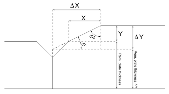
- X – Width of the taper.
- Y – Height of the taper.
- Factor – X/Y: Ratio of taper.
- Delta X – Extended width of the taper (ΔX).
- Delta Y – Extended height of the taper (ΔY).
- Angle in length dir. – Angle of the taper measured from plate direction (= inverse tangent of Y/X) (ɑ1).
- Angle in thickness dir. – Angle of the taper measured from thickness direction (= inverse tangent of X/Y) (ɑ2).
- Rem. plate thickness – Thickness of the plate minus the taper(s).
- Rem. plate thickness delta Y – Thickness of the plate minus the extended taper.
It is possible to add plain text between the selected fields by entering the desired text into the text box, and then pressing Enter.
Reduction/Taper Code Top
Sets the code for bevel top reduction.
Select from the available the fields. The code will consist of the values entered in the selected fields.
- X – Width of the taper.
- Y – Height of the taper.
- Factor – X/Y: Ratio of taper.
- Delta X – Extended width of the taper (ΔX).
- Delta Y – Extended height of the taper (ΔY).
- Angle in length dir. – Angle of the taper measured from plate direction (= inverse tangent of Y/X) (ɑ1).
- Angle in thickness dir. – Angle of the taper measured from thickness direction (= inverse tangent of X/Y) (ɑ2).
- Rem. plate thickness – Thickness of the plate minus the taper(s).
- Rem. plate thickness delta Y – Thickness of the plate minus the extended taper.
It is possible to add plain text between the selected fields by entering the desired text into the text box, and then pressing Enter.
Reduction/Taper Descr. Bottom
Set the description for bevel bottom reduction. The description is composed by filling in the fields selected in this setting.
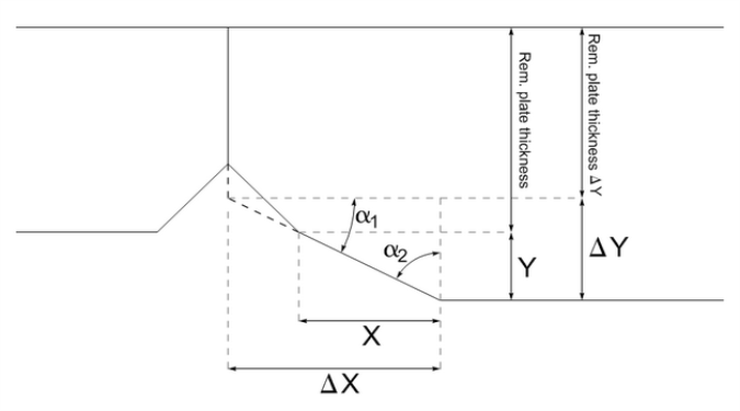
- X – Width of the taper.
- Y – Height of the taper.
- Factor – X/Y: Ratio of taper.
- Delta X – Extended width of the taper (ΔX).
- Delta Y – Extended height of the taper (ΔY).
- Angle in length dir. – Angle of the taper measured from plate direction (= inverse tangent of Y/X) (ɑ1).
- Angle in thickness dir. – Angle of the taper measured from thickness direction (= inverse tangent of X/Y) (ɑ2).
- Rem. plate thickness – Thickness of the plate minus the taper(s).
- Rem. plate thickness delta Y – Thickness of the plate minus the extended taper.
It is also possible to add plain text between the selected fields by entering the desired text into the text box, and then pressing Enter.
Reduction/Taper Code Bottom
Sets the code for bevel bottom reduction. The code is composed by filling in the fields selected in this setting.
- X – Width of the taper.
- Y – Height of the taper.
- Factor – X/Y: Ratio of taper.
- Delta X – Extended width of the taper (ΔX).
- Delta Y – Extended height of the taper (ΔY).
- Angle in length dir. – Angle of the taper measured from plate direction (= inverse tangent of Y/X) (ɑ1).
- Angle in thickness dir. – Angle of the taper measured from thickness direction (= inverse tangent of X/Y) (ɑ2).
- Rem. plate thickness – Thickness of the plate minus the taper(s).
- Rem. plate thickness delta Y – Thickness of the plate minus the extended taper.
It is also possible to add plain text between the selected fields by entering the desired text into the text box, and then pressing Enter.
Pos. Compensation Descr.
Define the text within the bevel description in the coded plate for bevels which have positive shrinkage compensation.
-
Bevel descriptions for coded plates are defined in System Management > Production > Plate Cutting Data > Bevel > Description (Standard) and Description (Variable).
-
Shrinkage compensation for predefined bevels is set in System Management > Construction > Welds/Bevels > Predefined Bevels, with the Compensation setting in the Weld tab.
Shrinkage compensation can also be set while inserting or modifying a single bevel.
Possible values are free text and the keyword Compensation which returns the amount of compensation.
Neg. Compensation Descr.
Define the text within the bevel description in the coded plate for bevels which have negative shrinkage compensation.
-
Bevel descriptions for coded plates are defined in System Management > Production > Plate Cutting Data > Bevel > Description (Standard) and Description (Variable).
-
Shrinkage compensation for predefined bevels is set in System Management > Construction > Welds/Bevels > Predefined Bevels, with the Compensation setting in the Weld tab.
Shrinkage compensation can also be set while inserting or modifying a single bevel.
Possible values are free text and the keyword Compensation which returns the amount of compensation.
Compensation Descr.
Define the text within the bevel description in the coded plate for bevels which have positive or negative shrinkage compensation, to be used if Pos. Compensation Descr. or Neg. Compensation Descr. has not been set. The text defined here will be shown for positive compensation if Pos. Compensation Descr. has not been set, and for negative compensation if Neg. Compensation Descr. has not been set.
-
Bevel descriptions for coded plates are defined in System Management > Production > Plate Cutting Data > Bevel > Description (Standard) and Description (Variable).
-
Shrinkage compensation for predefined bevels is set in System Management > Construction > Welds/Bevels > Predefined Bevels, with the Compensation setting in the Weld tab.
Shrinkage compensation can also be set while inserting or modifying a single bevel.
Possible values are free text and the keyword Compensation which returns the amount of compensation.
Pos. Compensation Code
Define the text within the bevel code in the coded plate for bevels which have positive shrinkage compensation.
-
Bevel codes for coded plates are defined in System Management > Production > Plate Cutting Data > Bevel > Code (Standard) and Code (Variable).
-
Shrinkage compensation for predefined bevels is set in System Management > Construction > Welds/Bevels > Predefined Bevels, with the Compensation setting in the Weld tab.
Shrinkage compensation can also be set while inserting or modifying a single bevel.
Possible values are free text and the keyword Compensation which returns the amount of compensation.
Neg. Compensation Code
Define the text within the bevel code in the coded plate for bevels which have negative shrinkage compensation.
-
Bevel codes for coded plates are defined in System Management > Production > Plate Cutting Data > Bevel > Code (Standard) and Code (Variable).
-
Shrinkage compensation for predefined bevels is set in System Management > Construction > Welds/Bevels > Predefined Bevels, with the Compensation setting in the Weld tab.
Shrinkage compensation can also be set while inserting or modifying a single bevel.
Possible values are free text and the keyword Compensation which returns the amount of compensation.
Compensation Code
Define the text within the bevel code in the coded plate for bevels which have positive or negative shrinkage compensation, to be used if Pos. Compensation Code or Neg. Compensation Code has not been set. The text defined here will be shown for positive compensation if Pos. Compensation Code has not been set, and for negative compensation if Neg. Compensation Code has not been set.
-
Bevel codes for coded plates are defined in System Management > Production > Plate Cutting Data > Bevel > Code (Standard) and Code (Variable).
-
Shrinkage compensation for predefined bevels is set in System Management > Construction > Welds/Bevels > Predefined Bevels, with the Compensation setting in the Weld tab.
Shrinkage compensation can also be set while inserting or modifying a single bevel.
Possible values are free text and the keyword Compensation which returns the amount of compensation.
Extra Length Descr.
Define the text within the bevel description in the coded plate for bevels with extra length.
-
Bevel description texts for coded plates are defined in System Management > Production > Plate Cutting Data > Bevel > Description (Standard) and Description (Variable).
-
Extra length forpredefined bevels is set in System Management > Construction > Welds/Bevels > Predefined Bevels, in the Extra length tab.
Extra length can also be set while inserting or modifying a single bevel.
Possible values are free text and the keyword Extra Length which returns the amount of extra length.
Extra Length Code
Define the text within the bevel code in the coded plate for bevels with extra length.
-
Bevel codes for coded plates are defined in System Management > Production > Plate Cutting Data > Bevel > Code (Standard) and Code (Variable).
-
Extra length for predefined bevels is set in System Management > Construction > Welds/Bevels > Predefined Bevels, in the Extra length tab.
Extra length can also be set while inserting or modifying a single bevel.
Possible values are free text and the keyword Extra Length which returns the amount of extra length.
Weld Text
Define the weld text. This setting defines the Weld Text field for several Production > Plate Cutting Data > Bevel > Description (Standard) and Description (Variable) settings.
Select from the available the fields:
- The Throat height field is filled with the throat height of the weld. If this field is selected and throat height is zero, the weld text will be empty.
- The Weld method field is filled with the weld method. Weld methods are defined in Construction > Welds/Bevels > Weld Codes > Welding Codes, Second Part.
User defined texts or environment variables (between % signs) can be added between the fields by entering the desired text or variable into the text box, and then pressing Enter.
Weld Code
Define the weld code. This setting defines the Weld Code field for several Production > Plate Cutting Data > Bevel > Code (Standard) and Code (Variable) settings.
Select from the available the fields:
- The Throat height field is filled with the throat height of the weld. If this field is selected and throat height is zero, the weld code will be empty.
- The Weld method field is filled with the weld method. Weld methods are defined in Construction > Welds/Bevels > Weld Codes > Welding Codes, Second Part.
User defined texts or environment variables (between % signs) can be added between the fields by entering the desired text or variable into the text box, and then pressing Enter.
Weld Text Maximum Distance
Define the maximum distance between the weld texts that are placed at the plate border. The distance is measured along the plate contour. If there is an odd number of weld texts, the middle one is left out (at the position of the bevel text).
Weld texts are defined by the Weld Text setting.
Model Scaling
Define the scale factor for the bevel model.
The scale factor can be set to depend on the length of the line where the bevel is located. In this case the setting should be defined as: <length 1> <factor 1> <length 2> <factor 2> .... <default factor>. For example: 1000 0.1 2000 0.2 3000 0.3 1.0, which means:
- Scale factor is 0.1 for lengths from 0 up to (and including) 1000.
- For lengths from 1000 up to (and including) 2000, the scale factor is 0.2.
- For lengths from 2000 up to (and including) 3000, the scale factor is 0.3.
For all lengths not covered by these settings, the default scale factor of 1 is used.
Bevel Output (Automated Bevels)
Select the output format for automatically placed bevels in the coded part DXF.
One or more of the following values and their combinations can be selected: Text, Model, Code, Weld Text.
The default setting is Text, Model, Code, Weld Text.
Taper Presentation Minimum
Set the minimum height that a taper must have to be presented in drawings, coded parts' DXF files, and in Hull Viewer.