Weld Codes
Construction > Welds/Bevels > Weld Codes
Define weld codes. Weld codes have a key role in controlling beveling and welding. A weld code normally consists of three parts which define the weld connection, welding method, and bevel type. For example, the weld code could be HN.18.X. The parts of the weld code are used in several functions, reports, and other production information. It is possible to only use the last part, bevel type, in the weld code.
Defining the weld codes
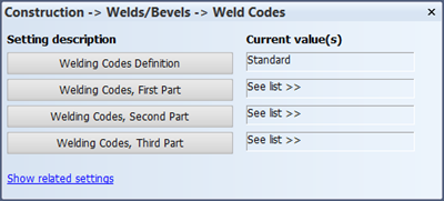
Welding Codes Definition
Normally weld codes consist of three parts. To only use the third part, bevel type, select User instead of Standard (default).
Welding Codes, First Part
The first weld code part is for the weld connection. It defines the way two plates are connected to each other for welding, and it consists of two alphabetic characters.
Note: This setting is not applicable if Welding Codes Definition is set to User.
In the Welding Codes, First Part dialog, a list of the already defined weld code first parts is shown, each on its own line. The first six lines are predefined weld connection types.
You can add new lines, and modify and delete the existing ones.
The first character of the weld code first part defines if the two plates have the same plane or not. If the parts have different in thicknesses, the first character also defines the side on which the difference in thickness is located. The following characters can be used:
- N – The connected plates have the same plane and have the same thickness.
- B – The connected plates have the same plane and different thicknesses. The thickness difference is located on This side in the plate's viewing direction.
- O –The connected plates have the same plane and different thicknesses. This thickness difference is located on the Other side in the plate's viewing direction.
- H – The connected plates have a T connection.
The second character of the weld code first part defines whether tapering is used between plates that have different thicknesses. The following characters can be used:
- N – Tapering is not used.
- A – Tapering is used.
Welding Codes, Second Part
The second weld code part defines the welding method: manual, automatic, and so on.
Note: This setting is not applicable if Welding Codes Definition is set to User.
A list of the already defined weld code second parts is shown, each on it own line. The first six lines are predefined welding methods.
You can add new lines, and modify and delete existing ones by entering values in the fields at the top of the dialog. The fields represent the five parts of the weld code second part:
- The first part, Method, defines the welding method code.
- The second part, Factor, defines a factor that indicates the percentage that is actually welded (multiplication factor).
- The third part, Func.descr., defines the welding method description shown in the dialogs of functions that use this information.
- The fourth part, DXF.descr., defines the welding method description used in DXF files.
- The fifth part, Drw.descr., defines the welding method description used in drawings.
Welding Codes, Third Part
The third part of a weld code defines the bevel type. There are nine standard bevel types that can be used: I, V+, V−, X, X+, X−, Y+, Y− and K.
A list of the already defined weld code third parts is shown, each on it own line.
You can add new lines, and modify and delete existing ones. The first six lines refer to predefined bevel types.
See also Bevels and Welding information in the Generating Production Information User's Guide in the Help.