Bevel properties for predefined bevels
The system administrator can define predefined bevels in System Management > Construction > Welds/Bevels > Predefined Bevels.
In CADMATIC Hull version 2025H1, changes were made to the predefined bevel properties. Extra length and shrinkage compensation were made bevel properties, and the On entire relation property was removed.
The original automatic project conversion that the system performs when opening a project which was created in an earlier Hull version did not take into account these changes. This would cause automatic predefined bevels in converted projects to lose their extra length if the bevels were modified or if Bevel Generator was run.
In Hull version 2025H1R4, the project conversion was updated so that it handles the changes made to the predefined bevel properties in the 2025H1 main version. The updated conversion adds extra length and shrinkage compensation to the bevel properties and removes the On entire relation property.
If project conversion was run in a Hull 2025H1 version earlier than 2025H1R4, the conversion of the predefined bevels can be done separtely by running the following command in the Hull Command Window:
do lb1/modify_normdir,ConvertPDB243
Also, if the project is converted with the original conversion and the command has not been run, when a predefined bevel is modified in System Management > Construction > Welds/Bevels > Predefined Bevels, the properties of that bevel type are updated to the new standard.
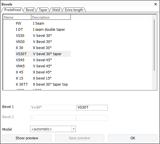
You can adjust the properties of predefined bevels while inserting or modifying single bevels in the 2D-Contek & 3D-Contek and Shell applications, in the Bevel dialog which opens when you start the insert or modify function. The Predefined tab is active when you start the functions. Select the predefined bevel that you want to insert, or to apply if you are modifying an existing bevel.
The bevel properties are grouped into tabs, as follows:
A Settings tab is available in the in the System Management application for defining how the bevel should react on different plate thicknesses.
Bevel tab
Depending on the selected bevel type, the Bevel dialog displays a different set of settings and options. Only the settings and options that are applicable for the selected bevel type are shown.
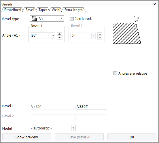
The options are as follows:
-
Bevel type – Set the type of bevel to be applied. See Bevel types.
-
Angle – Set the angle of the bevel.
-
Bevel – Sets the height of the bevel.
-
Nose – Sets the height of the root face.
-
Join bevels – When selected, forces the same value for Bevel 1 and Bevel 2.
-
Angles are relative – Switches between relative and absolute bevel angles. A bevel on a plate can be relative to the construction that the plate is touching. When the plate is touching slanted and curved construction, the start and end angles of the slanted construction are used to create a bevel that runs from one end to the other linearly.
 Show/hide example
The example below shows a deck connected to the hull. A V bevel is used with an angle of 0°. The slanted lines indicate the shape of the hull to which the plate is related. Line A shows the angle of the hull at the start and line. Line B shows the angle at the end of the bevel.

Absolute angle

Relative angle
These angles are also shown on the dialog.
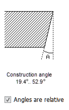
Construction angle
Construction angle is the angle between the beveled edge of the plate and the side of the other plate touching the beveled edge.
With V bevels, the construction angle is the average of the angle at one end point of the bevel and the angle at the other end point of the bevel. For example, if the construction angle of the beveled plate edge to the conneted plate is 19.4° at one end of the bevel, and 52.9° at the other end of the bevel, the construction angle is (19.4°+52.9°)/2 = 36.15°.
-
With V bevels, the construction angle is subtracted from the bevel angle when the bevel is a V+ bevel, and added when it is a V- bevel
Whether the construction angle is positive or negative depends on which side the angle is located, relative to the view direction.
-
The angle is positive if it is located on the side opposite to the view direction.
-
The angle is negative if it is located on the side of the view direction.
See Angles in the different connections.
Taper tab
Enable and modify tapering properties of the bevel. The settings and options shown wary according to the selected Position.
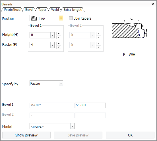
The options are as follows:
-
Position – Enable or disable tapering, and set the position on the plate where the taper is applied.
-
Height – Ses the height of the taper.
-
Factor / Angle / Width – Set the angle of the taper, the width of the taper, or the width/height ratio for the taper.
-
Specify by – Set which of the three settings above are shown in the dialog.
-
Join tapers – When selected, forces the same values for Bevel 1 and Bevel 2.
The system will adjust and choose the taper according to the situation. When the correct taper for the situation is not known, you should define the taper on both sides.
A taper will be added to the production data when the thickness difference is more than the taper setting. Taper information is always available at the drawing level.
Weld tab
Modify the weld connection settings of the bevel.
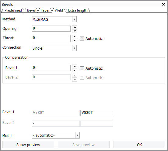
The options are as follows:
-
Method – Select the weld method. The available options are set in System Management > Construction > Welds/Bevels > Weld Codes, in Welding Codes, Second Part, Func.descr. for each weld code.
-
Opening – Set the size of the weld opening (mm).The opening defines the distance between the parts to be welded. It does not affect the size of the parts. The minimum value for the opening is 0.
-
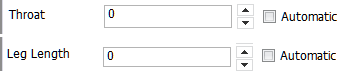
Throat height or Leg length – Define either the throat height or leg length of the weld (mm).
Which one is shown depends on the System Management > Construction > Welds/Bevels > Settings > Weld Size Parameter setting. Throat height is the default.
When Automatic is selected, the system will calculate the value automatically based on Weld factor rules. The input field is empty, and a value cannot be entered. When Automatic is not selected, the last set value is shown and can be changed by entering a value or using the arrow buttons.
-
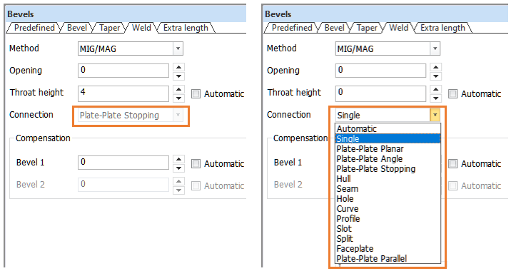
Connection – Select the connection type for the bevel.
When inserting a bevel, the connection type which is applicable for the situation is shown. When modifying a bevel, the connection type which has been set when creating the bevel is shown. The connection type can only be changed if the type is Automatic or Single.
Note: If inserting a bevel fails, recalculate the involved plate with the Update unchanged 3D models option selected.
-
Compensation – Set the shrinkage compensation for the bevel (mm). The compensation can be positive or negative. When two bevels are involved, the compensation can be distributed between the bevels by setting a value separately for both of the bevels.
Note: Compensation and extra length have a cumulative effect on the plate edge.
When Automatic is selected, the system will calculate the compensation automatically based on the rules set in System Management > Construction > Welds/Bevels > Compensation Rules. The input field is empty, and a value cannot be entered. When Automatic is not selected, the last set value is shown and can be changed by entering a value or using the arrow buttons.
Extra length tab
Set extra length for the bevel(s).
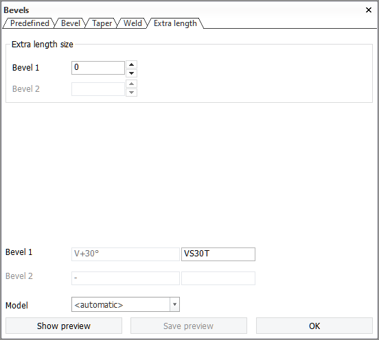
Extra length size – Set the size of extra length on the plate edge (mm). The value can be positive or negative.
Note: Compensation and extra length have a cumulative effect on the plate edge.