Lines
Production > Plate Cutting Data > Marking > Lines
Minimum Length Of Marking
This setting determines the minimum valid length of a marking. Markings longer than or equal to the value set here are placed on the coded part.
A value of zero means that all markings are shown regardless of their length.
Create Marking Lines
Marking lines can be shown on one side or on both sides of a part.
Select from the following options:
- From both sides – Markings from both sides of the part are shown on one side of the part.
- Only viewing side – Only markings that are on the viewing side of the part are shown.
- Double sided – Markings are shown on both sides of the part.
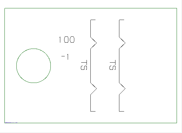
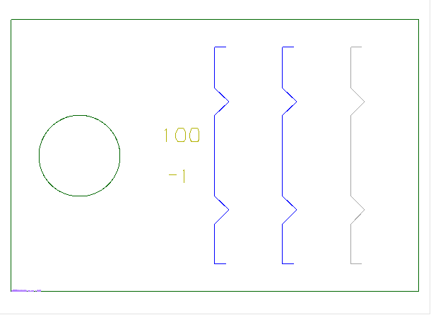
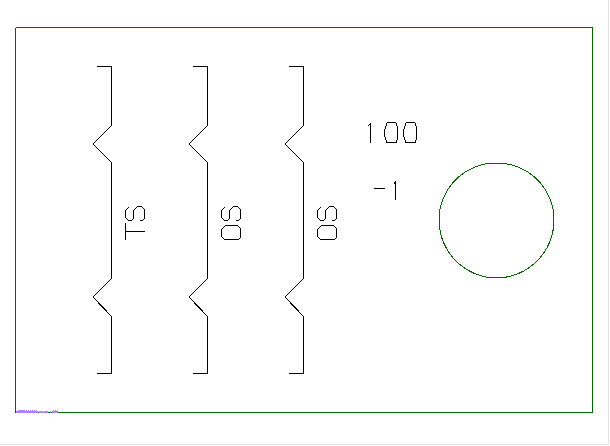
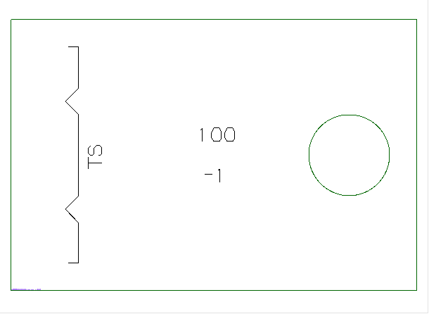
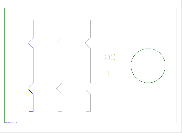
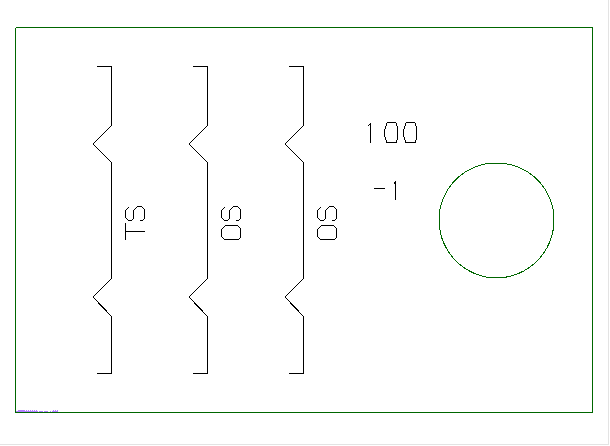
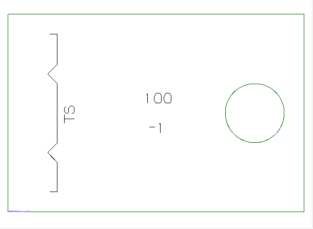
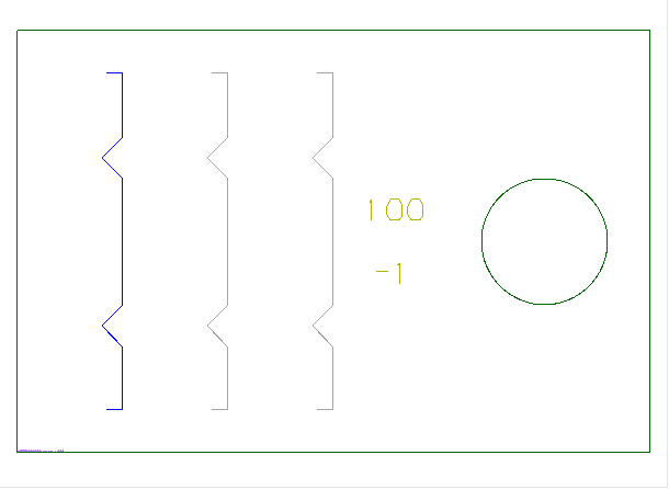
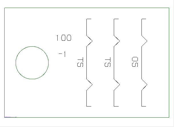
The table below gives examples on how the different marking line settings work in combination with mirroring. In the images showing the coded part "TS" stands for "this side" and "OS" stands for "other side".
Note: When mirroring is off, the direction goes the following way: aft to fore, port to starboard, bottom to top.
The construction of the plate used in the examples is the following:
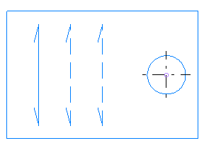
|
Marking side setting |
From both sides |
Only viewing side |
Double sided |
|---|---|---|---|
|
According to Mirror Conditions |
|
|
|
|
Opposite to Mirror Conditions |
|
|
|
|
Standard viewing direction |
|
|
|
|
Non-standard viewing direction |
|
|
|


For more about mirroring, see Production > Plate Cutting Data > Mirroring Conditions.
For information on the marking side settings, see Production > Plate Cutting Data > Marking > Settings.
Markings In Adjacent Blocks
Marking lines of profiles and construction in adjacent sections are computed automatically by default.
Set this setting to Disabled if these markings should not be processed. The advantage of this is that the coding process is faster because there are less calculations to make.
Holes from adjacent blocks are processed only if this setting is set to Enabled.
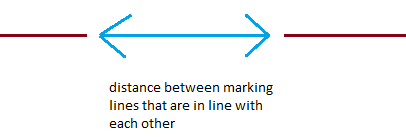
Combine Marking Lines Distance
The system automatically combines marking lines that are in line with each other or on top of each other. This prevents the powder marking device on the cutting tool from applying the same marking several times on the plate.
Markings that are in line with each another and the maximum distance between them does not exceed the value set here are also automatically combined.
Remove Lines In Holes
Show or remove parts of marking lines that are positioned in holes.
A marking line can be partially positioned in a hole. When this setting is set to Disabled (default), the part of a marking line that is positioned in a hole is shown. When set to Enabled, the part of the marking line that lies in the hole is removed.
No Markings Near Plate Border
Set the minimum distance from plate border that a marking must have to be shown. Markings closer to the plate border than set here are not shown.
In some cases, for instance in case of a slanted part, markings may appear very close to the plate border and it may be useful to hide markings that are too close.
Only those marking lines that are completely positioned within the set value are hidden.
Markings At Centre Line
Set the minimum distance from the center line that a marking must have to be shown. Markings closer to the center line than set here are not shown.
Setting the minimum distance can be useful in cases where you want to use a reference line at a specific breadth, and therefore want to hide all marking lines that would lead too close to the reference line.
Distance Marking-Contour
Define how close the end of a marking line is allowed to get to the contour of a part. Marking lines will stop at the set distance.
With this setting you can prevent the end of the marking line to come too close or cross the part contour.
Only positive values are allowed.
Note: This setting considers part number texts. Part number texts are not allowed closer to the part contour than the distance set here. It is possible that a marking is not shown on the coded part because of the part number text coming too close to the part contour. Try increasing the Distance Marking-Contour value if there are part numbers missing. You should consider this especially if a prefix and/or a postfix is defined for the part number text, making the text take up more space. The part number prefix and postfix are defined with the Lug Partnumber Prefix and Lug Partnumber Postfix settings, respectively.
Drawn Marking Line Parts
Set the amount of marking parts that are drawn, from the start and from the end of the marking line.
A value of 1 means one line or a radius. Valid values are zero and any positive whole number. A value of zero indicates that the complete marking line is drawn.
Plate Markings, This Side
When set to Enabled (default), marking lines texts are added to the viewing side of the plate.
When set to Disabled, no text is added to marking lines.
Plate Markings, Other Side
When set to Enabled (default), marking lines texts are added to the opposite of the viewing side of the plate.
When set to Disabled, no text is added to marking lines.
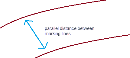
Combine Marking Lines Margin
Set the threshold value for combining two straight marking lines with parallel distance. Straight marking lines that have less parallel distance between them than the value set here are combined into one line. If the distance exceeds the value set here, the lines are not combined.
The purpose of this setting is to preserve a clean view even when there are overlapping marking lines present.
Combine Bent Marking Lines Margin
Set the threshold value for combining two bent marking lines with parallel distance. Bent marking lines that have less parallel distance between them than the value set here are combined into one line. If the distance exceeds the value set here, the lines are not combined.
This setting defines the parallel distance between bent marking lines, from which the system is allowed to combine the two lines to one line. The purpose of this setting is to preserve a clean view even when there are overlapping marking lines present.
Marked Hole Centre Line Marking
Enable or disable centre lines for marked holes on the coded part. Set to Disabled by default (centre lines are not shown).
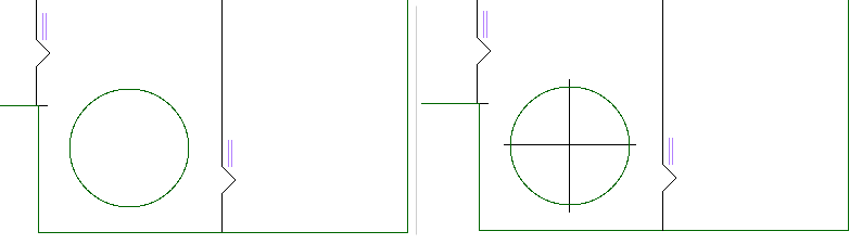
Hole on coded plate without centre lines (left) and with centre lines (right)
Template Line Redundancy Threshold
Define the maximum allowed overlap of template marking lines with inner construction lines. The overlap is expressed in the percentage of the template line's total length.
If a template marking line's overlap is larger than the percentage value set here, the template marking line will not be visible on the part.
When template marking lines are close to inner construction, markings of the template lines are filtered out to avoid cluttering. Their symbols however will still be present, which helps placing templates accurately.
To detect which lines need to be filtered, the system finds the overlapping portion of each line pair, where one line is a template marking line and the other is inner construction. The overlap is defined as the segments of one line that have a short projection length to the other line.
Percentages from 0 to 100 can be used.