Settings
Production > Plate Cutting Data > Shell Plates > Settings
Method of Forming
Define the method that will be used to form your shell plates at the production site.
The flattening of the shell plate can be calculated in various ways depending on the method that is intended to be used for unfolding the plate into its final shape.
There are two options available:
- Cold forming
- Line heating
The plate expands when using cold forming during the bending process, and contracts when using line heating. Therefore, the plate needs to be cut smaller in case of cold forming, and bigger in case of line heating. Selecting the method of forming helps the system to achieve maximum accuracy during the unfolding process.
Tolerance for Connected Shapes
Connected shapes are designed by the experts who create the fairing of the ship. This setting defines the maximum allowed distance in millimeters between these connected shapes.
This setting applies both to the gap between connected faces, and to the distance between the contour and the surface. The image below illustrates the distance the setting affects.
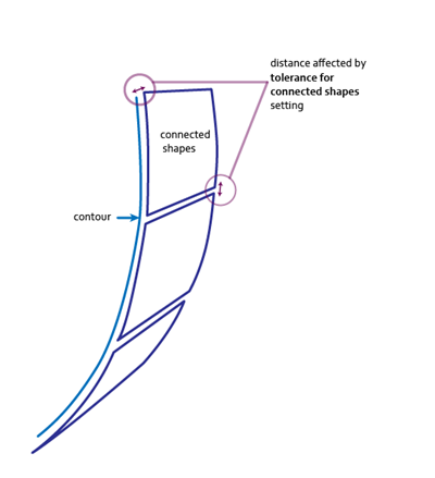
This value also directly affects the minimum dimensions a face must have to avoid collapse: faces that have a gap smaller than the value in this setting will be considered as connected by the system. For this reason it is not recommended to set this value much higher than the default setting.
Meshing Tolerance per Plate Length
Set the maximum allowed distance between the nodes of the discreet and continuous geometry of the shape along the surface (geodesic elongation). The value set here defines how much shift is tolerated between the nodes, in millimeters per meter.
If this value is set higher that 0.3, and Strain Optimization is disabled, the system will prompt you to enable Strain Optimization. When Strain Optimization is enabled, the system will automatically optimize the meshing tolerance instead of using the value set here.
Note: Too small tolerance slows down the calculation process. Higher tolerance speeds up the calculation process, but may have negative results for production.
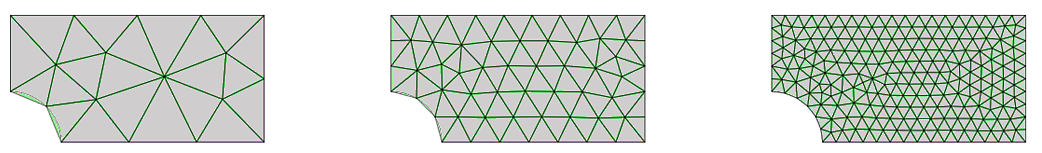
When meshing the surface of the shell plate, the continuous geometry of the plate is defined in connected nodes (discreet geometry). The images below show how the number of nodes changes the meshing of the same plate.
After discretizing the geometry of the plate, points of the continuous geometry and points of discreet geometry will slightly shift from each other. This setting defines the maximum allowed distance between the nodes of the discreet and the continuous geometry of the shape along the surface (geodesic elongation).
The image below shows geodesic elongation between the nodes.
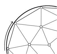
This setting defines how much shift is tolerated between the nodes in millimeters per meter. The higher the tolerance set in this setting, the lower the number of the nodes in the mesh will be.
This setting and Number of Nodes Allowed in Mesh correlate with it each other and the latter setting is more dominant. In cases when the mesher returns with more nodes than specified in Number of Nodes Allowed in Mesh, the system automatically restarts the process with an increased tolerance.
Number of Nodes Allowed in Mesh
Define the maximum allowed number of nodes produced by the meshing process. You can set a maximum amount of nodes to avoid excessive calculation time.
The Meshing Tolerance per Plate Length setting is constrained by this setting. This means that in cases when the meshing process returns more nodes than specified in this setting, the system automatically restarts the process with an increased tolerance.
Min. Shift to Continue Unfolding
The unfolding process is done by a non-linear algorithm. You can define the minimum shift between the nodes in millimeters when the algorithm should stop the unfolding process.
The algorithm arrives to the ideal result by doing multiple calculations with slightly adjusted values. When it reaches the value defined in this setting, it stops the calculation and remains at it's last result.
This means that setting this value too small results in a may drastically increase the time required for the unfolding process to complete. You can adjust this value to save time while coding the plates.
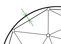
Max. Deflection Discretizing Curves
Define the maximum allowed deflection in millimeters when the marking and cutting lines on the shell plate surface are discretized.
The image below shows the distance of deflection between the projected lines and the surface.
Meshing Tolerance Warning Text
Define the text for the warning that is shown in shell plate elongation reports when the hard-coded maximum meshing tolerance of 0.1 is exceeded. A warning may be necessary when the number of mesh nodes on the plate has been decreased or when the plate is fairly big. In such cases it is possible that the system actually uses a meshing tolerance bigger than the maximum. Too big meshing tolerance can lead to inaccurate elongation information in the shell plate elongation report. The plate should be split if the maximum meshing tolerance is exceeded.
The setting value can contain free text and the following fixed fields:
-
MaxDeflection – Replaced in the elongation report with the value defined by the Meshing Tolerance per Plate Length setting above.
-
ActualMeshingTol – Replaced in the elongation report with the meshing tolerance that is actually used (that is, the tolerance value exceeding the maximum).
The default setting is "Warning meshing tolerance changed from "MaxDeflection" to "ActualMeshingTol "!".
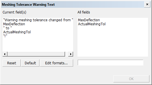
Field format codes can be used to format the fields. Click Edit formats to open the Edit field formats dialog where you can edit the formats. See Field Format Editor.
Important: For the warning to be shown in elongation reports, keyword mesh_tol_warning must be added as a comment to the shell plate elongation report template in the desired cell. See Meshing tolerance warning in the Elongation Report Template help topic.
Roller Line Text
Define the description added as a text label to the roller line in the DXF output. This text can have up to 32 characters. The default value for this setting is ‘roller’.
The image below shows the roller line on a coded shell plate.
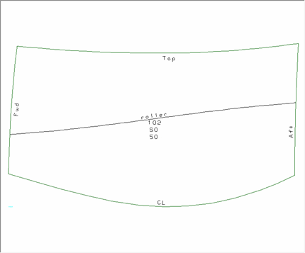
See Including roller lines in the Shell Plates Reference Guide for more information about roller lines.
Roller Line Grid Distance
Define the spacing between the roller line grids in millimeters. The roller line will not be calculated if this value is below 100 mm. Note that if the shell plate is not big enough to support the pre-set grid spacing value, the system automatically halves the value until at least three grid lines fit on the shell plate, or the distance between grids becomes less than 100 mm.
See Including roller lines in the Shell Plates Reference Guide for more information about roller lines.
Flatness Threshold Radius
Set the minimum radius value for shell plates in mm.
See Using item information to determine curvature in the Shell Plates Reference Guide for more information on this setting.
Strain Optimization
When enabled (default), the system will unfold the shell plate with optimal meshing tolerances.
If you disable Strain Optimization, the value set in Meshing Tolerance per Plate Length is used. If the value is set higher than 0.3, the system will prompt you to use a lower value or enable Strain Optimization.
Note: This behavior is only valid for production output. The Meshing Tolerance Per Plate Length value is always used in the Hull server. It is recommended to use the default value Enabled for production data.