Coding composite profiles and shell frames
The coding of composite profiles will produce two or three DXF files depending of the profile type:
- T bars and (un)equal angle bars will produce 2 DXF files: one for the body and one for the flange.
- I and H beams will produce 3 DXF files: one body and two for the flanges.
The coding of composite shell frames will produce two DXF files (one for the body and one for the flange). Only shell frames positioned in one plane (in-plane shell frames) produce two DXF files, other shell frames will produce one DXF file.
Note: These shell frames will only be coded if the setting Code Shellframes is set to Handle all as straight. For more information, see System Management application > Production > Plate Cutting Data > Shell Frames.
The naming of the DXF files is according to the usual file name convention. The only difference is that the part numbers will get a prefix and a postfix. The prefix and the postfix will make the name of a DXF file unique and will identify whether the file is for a body or a flange.
You can set up the prefixes and postfixes in the System Management application in Production > Plate Cutting Data > Settings.
To Code Composite Profiles and Shell Frames
- Select the Production Information function in the Production tab of 3D-Contek application. The Create Production Information dialog box appears.
- Select the Code block option and for non-planar shell frames also select Sketches.
- Click OK to code the block.
- To see the DXF files close the dialog box and select Modify Coded in the Production tab in the 3D-Contek application. You can now see all coded parts and you can select the composite profiles based on their prefixes and postfixes.
Markings on DXF for composite profiles and shell frames
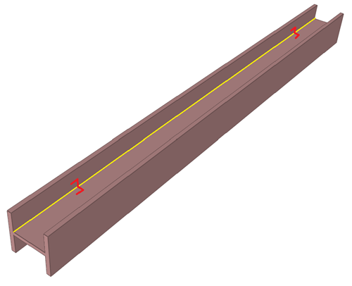
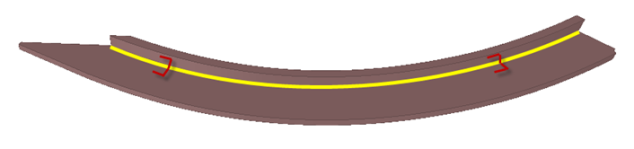
The only markings on DXF for composite profiles and shell frames are mounting lines and markings that show the connection between the body and flange(s).
The direction of the profile or shell frame determines the type of mounting lines that appear on the parts. Mounting lines are only displayed on the body part. Maximum two mounting lines are printed on the body, showing the position of the flange(s).
If more than two mounting lines intersect the profile or shell frame, only the ones nearest to the profile or shell frame ends are marked.
The images below demonstrate the markings showing the connection between the body and the flange.
Marking lines of the body on the profile or shell frame flange(s) are not displayed in case of angle bars, because in this case the marking like would be at the edge.
In case of shell frames, the contour of the shell frame body including the end shapes is used for coding, but not extra length. The extra length values are added to the ends of the shell frame.
In case of shell frames, the flange size is measured along the neutral line. This means that the flange's height is at the top of the shell frame minus half of the flange thickness. The end shapes are taken into account in determining the length. Also the extra length is added to the neutral line.
The texts along the markings on the profile and shell frame body will show the prefixes and postfixes for the profile flange.
The text on the profile or shell frame body along the markers touching the (first) flange will be:
<Main Flange Prefix><Main Flange Postfix>
And for the second flange (in case of some profile types):
<Second Flange Prefix><Second Flange Postfix>