Modifying the plate cutting data
In 3D-Contek, you can check the output of coded parts in DXF format. If necessary, you can also modify the output. Select Production > Modify Coded to open the Select drawing dialog. The first part in the list will be shown.
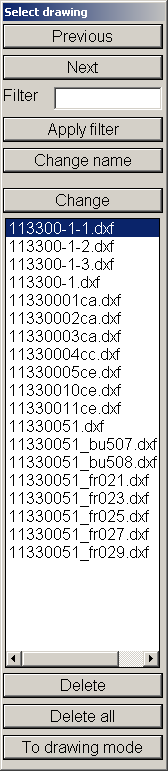
Previous and Next – Click to see the previous or the next part in the list.
Filter – Enter a character string to filter the parts to be shown. If the character string is present in the DXF file name, only these parts are shown in the list after clicking Apply filter.
Change – Open the Modify drawing dialog, where you can modify the selected part with a function common for changing parts. For more information, see Change mode.
Delete and Delete all – Delete the selected part or all DXF parts. The file or files of the selected part(s) will be deleted from the directory structure. Note that recovery is not possible – if you need the part, you have to recalculate it with the Create Production Information function.
To drawing mode – Hide the Select Drawing section. You can then use the normal 2D drawing options to change the part. Using Save or restarting the Production > Modify Coded function will again show the section and save the changes. Kill All prevents anything from being changed.
The Save As function saves the part as a drawing and not as another part.
The inkjet separator text will be shown with the normal Contek line spacing when To drawing mode is used. After saving, this will be corrected automatically in the part to the line spacing for Modify Coded.
Change mode
When you click Change, the Modify drawing dialog opens and the selected part can be modified with a function common for changing parts. The Abort button can be used to go back to the previous dialog. Changes will not be saved when using this function.
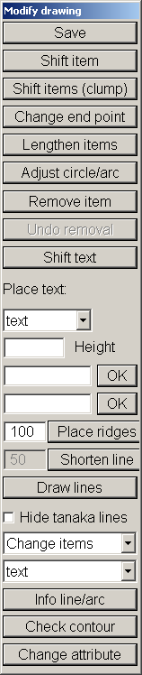
Save – Save the modified part.
Note: If the plate cutting data DXFs are layer based (which is defined in System Management setting Production > Plate Cutting Data > DXF Output > Layers Colours 1 > Use Colour Number Or Layername), make sure that all used layernames have a unique corresponding pen number defined in the various Layers Colours 1 and Layers Colours 2 settings. Otherwise saving the modified coded part might disrupt the layers inside the DXF file. To fully control this, you also need to create a data file called dxfmodlayer.dat in the active norms folder which contains on each line a unique pen number followed by the corresponding layername.
Shift item – Move the selected line or text (item) by means of the a shift vector (n100 or e50) or in two directions (n100&e50).
Shift items (clump) – Group items and then move them by dragging. All items within the box will be selected.
Change end point – After selecting a line end point, this end point and the connected line will be changed to a new selected end point. This will continue until another function will be started.
Lengthen items – This function will lengthen or shorten two lines or circles. The end points of the line which is the nearest to the selection point will be changed. The circle will be changed always at that end point that is the closest to the circle.
Adjust circle/arc – Change the radius of a circle or arc.
Remove item – Delete a line, circle or text.
Undo removal – Cancel the last delete action.
Shift text – Move text items by dragging them to another position. This will continue until you start another function.
Place text – Add text to the drawing by entering it in one of the two fields, that is, SB and PS. The text will be added in the drawing when you click OK. Define the height of the text in the Height field. If text was added before, this text is used by default in the first field. Also the height will be used by default. When you click one of the two OK buttons, the program asks to provide two points. These points will be used to calculate the angle at which the text must be placed. Then drag the text to the desired position. In some cases it is useful to add attribute text to plates, to avoid manual changes with this function.
Place ridges – With this option it is possible to place ridges in the contour, The input field to the left of the option button is used the determine the length of the ridges. If no value is entered, a default value of 100mm is used. After the item in which the ridges have to be placed is selected, the user is asked how many ridges have to be placed. Subsequently the ridges are evenly spaced over the selected item.
Shorten line – With this option, a line or circle can be shortened to the nearest side of the selected item. The value for shortening can be entered in the input field to the left of the option button.
Draw lines – Draw extra line elements. After clicking this, you can select the line type in the Select line dialog that opens next to the Select line dialog.
Hide tanaka lines – Hide marking lines. If the contour line should be modified, it is easier when these lines are not shown. Clear the checkbox to have the lines shown again.
Change items – Change the type of the selected line. The type of line/arc of the selected item can be changed in the drop-down menu under Change items.
If you select Copy items, it is possible to copy the item and change the type all at the same time.
Info line/arc – Add information about a line or an arc.
For a line, the following information is given:
- First point – x, y, z coordinates of point 1
- Second point – x, y, z coordinates of point 2
- Delta x – Difference in the x direction between points 1 and 2
- Delta y – Difference in the y direction between points 1 and 2
- Delta z – Difference in the z direction between points 1 and 2
- Angle – The angle between points 1 and 2
- Length – The length of the line
For a circle or arc, the following information is given:
- Starting point – First point on the arc
- End point – Second point on the arc
- Middle point – Middle point on the arc
- Start of angle – Absolute angle of first starting point
- End of angle – Absolute angle of second starting point
- Angle – Angle of the arc
- Circle radius – Radius of the circle or arc
- Length of arc – Length of the arc measured along the arc
Check contour – Check lines. After clicking this, select an outer or inner contour. This line in combination with others from the same line type will be checked. It will check for a closed contour and if all lines or circles of the same type are used. If there is a gap between elements, the length of this gap is shown in the Deviation window. If you click one of the lengths presented in the list, the mouse pointer will move to the location of that gap. If you select Rest lines, all lines that do not belong to the selected contour but have the same type will be highlighted.
Note: An outer contour must be a closed contour. There is one exception if a ridge is part of the contour.
Change attribute – Show and change logistical attributes of the part. Only single logistical attributes defined in the DXF can be changed. The logistical attributes will be copied from another part when you select the part. Attributes that are composed of 2 or more attributes can only be changed when 1 of the attributes of which it is composed is changed.