Profile sketches for composite profiles
A composite profile must be coded before the profile sketch can be created, because the flange part in the profile sketch is taken from the flange DXF file. This means that the DXF file for the flange must be available before the profile sketch is generated. See Coding composite profiles and shell frames for more information on coding composite profiles.
To create profile sketches, select Sketches in the Create Production Information dialog.
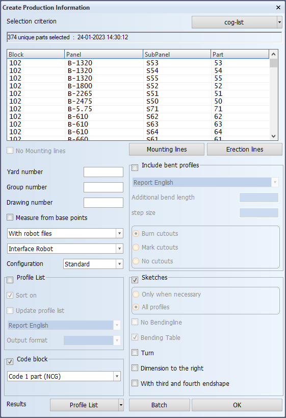
The coding and sketch creation can be performed at the same time by selecting both Code block and Sketches in the Create Production Information dialog. See Create Production Information. In this case the flange DXF will be created first and it will be available for the sketch generation process.
Presentation of the profile body and flanges in profile sketches
There are three ways to present the profile body and the flange(s) in profile sketches.
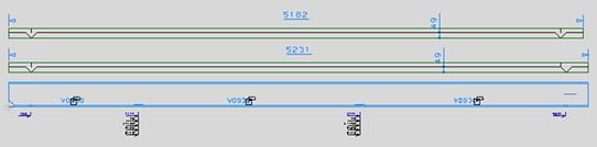
1. Body and flange attached in the same sketch
This is the standard presentation of the profile body and the flange in a profile sketch.
To use this presentation, select With third and fourth endshape in the Create Production Information dialog.
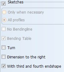
If you do not select With third and fourth endshape, only the profile body will be shown in the profile sketch.
2. Separate body and flanges in the same sketch
To have the profile body and flange(s) appear separately in the same sketch, do the following:
-
Select With third and fourth endshape.
-
Make sure that Real Profile-Length In Sketch is set to Yes in the System Management application, Production > Profile Sketch > Settings. Without this setting the flanges will not be displayed in the profile sketch.
When the profile has two flanges, the first flange will be positioned above the profile body, and the second flange above the first flange (and not below the body).
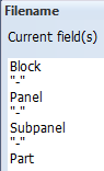
Important: The naming of the flange DXF file and the profile sketch must be in line, or the DXF file is not found, and the flange(s) will be left out from the profile sketch. Check that the DXF file name structure that is set in the System Management application, Production > Plate Cutting Data > DXF Output > Settings matches the ROBOTFILENAME set in first line of the ncgrobot.ind file:
|

|
3. Body and flanges in separate sketches
It is possible to generate separate sketches for the profile body and the flange(s).
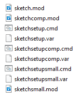
The sketch layout file for composite profiles, sketchcomp.mod and its related files, must be present in the %ncgnorms%\sketch folder for this to work.
Do the following:
-
Select With third and fourth endshape.
-
Make sure that Real Profile-Length In Sketch is set to Yes in the System Management application, Production > Profile Sketch > Settings.