Settings
Production > Profile Sketch > Settings
Profile Sketch Layout Filename
Set the file name with the layout for the profile sketch.
Use Leadin On Drawing
When disabled, no lead in is created for holes.
Dimensioning From Right Side
When enabled, dimensions start at the right side of the sketch. For some customers the correct value is automatically used if necessary.
Real Profile-Length In Sketch
Determine if profiles should be presented with their real lengths in a profile sketch.
- When set to No, the smaller profiles will be stretched to fit between the Model, bottom left and Model, bottom right fields in the sketch layout.
- When set to Yes, the profiles will be shown with their real lengths in the sketch. The sketch will have two markings placed at the real start and end points of the profile at the height of the Length field in the sketch layout
See also Influencing the way smaller profiles are displayed in the Managing Production Information Administrator's Guide.
Show Straight Shellframe Bevel
When enabled, bevel code information for straight shell frames will be visible in the profile sketch.
Bevel Indication On Drawing
When set to Short, no parentheses ( ) are used for bevel indications in the profile sketch.
Dimensioning Starting Point
By default, attribute dimensions are measured from the absolute starting point (extra length) of a profile.
Dimensions can be measured relatively from the position of the endshape by selecting From endshape.
Examples of both settings are shown in the picture below. For the upper profile, the default measurement is used. For the lower profile, measurement from the endshape is used.
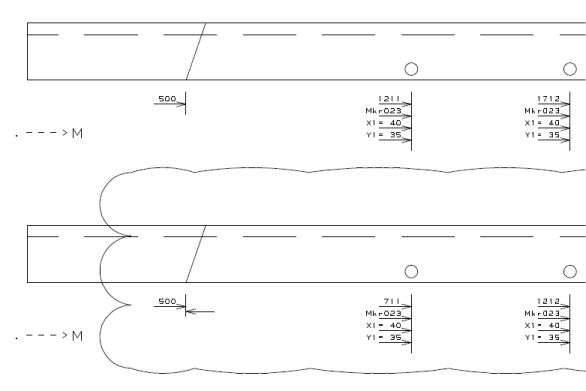
Note: This setting is applicable only if the Dimensioning From Right Side setting is set to Disabled.
Slanted RFH Warning
Define the text that is added to a sketch, when an Outfitting hole direction deviates more than 10 degrees from the normal direction of the profile or shell frame. The default text is "Hole size deviates", and it is used also when the field is left empty.
Output Directory TIFF
Set the (relative) output directory for TIFF files. The root directory is defined with Production > General > Output Directory.
In addition to the fields specified in the logistical layout, the following fields can be used:
- ObjectNumber – The object number of the project.
- ProjectName – The name of the project.
- BlockGroup – The group that the block is assigned to.
- BlockName – The name of the block.
- BlockNumber – The number of the block.
- Partcode – Defines that the construction part specific part code is used. This code is specified as Part code in the Logistics > Prefixes And Part Codes setting.
- PlateRecNr – The plate record number of the part, or that of its parent plate-like part if the part has no plate record itself.
- AttRecNr – The attribute record number of the part. The number is 0 if the part has no attribute record.
- WBD Branch 1..9 – The Work Breakdown name for a specific level.
It is also possible to add text or environment variables, enclosed between % signs, to the fields.
See also Editing field formats.
Note: If this setting is set to Block, the system will generate DXF files even when the robot file output is set to None in the Create Production Information function.
Sorting Method
Define the method used for sorting. The following methods are available:
- Standard – Sort by part number (this can also be a name).
- Include Panel Number – The panel number is added to the part number, then sorting is performed
- Use Only Numeric Part Number – Only the numeric part (no alphabetical characters) of the part number is used for sorting.
Base Start Point Is Zero Length
With the default setting value No (default), the total profile length in profile sketches includes the extra length that is manually added to the profile end type. The system takes the profile length + extra length value from the $BASIS variable in the robot layout file for profile sketches (ncgrobot.ind) when generating the sketches. $BASIS is the profile length including the extra length.
When set to Yes, the system uses the extra length defined in the type file of the profile end type. The system uses the value of the $MBASIS variable in the robot layout file, and adds to it the extra length defined in the profile end type file. $MBASIS is the length between the profile's start and end base points. This means that extra length is measured from the profile base points.
Important: Extra length information must be included in all profile end type files before setting the value to Yes. For information on how to define extra length in profile end type files, see Automatic extra length definition for profiles.
Also, some changes are needed in the robot layout file that is used for profile sketches. See Robot layout file.
See also Extra length in profile sketches.
Bend Length Calculation
When set to Yes (default), the system includes the end type length in the user-defined additional bend length when generating profile sketches and robot files for bent profiles. The total bend length is measured from the profile's base point.
When set no No, the system will add the additional bend length to the end type length to get the total bend length.
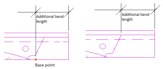
Left: Additional bend length includes end type length (setting value Yes).
Right: Additional bend length added to end type length (setting value No).
Additional bend length for bent profiles can be defined when generating production information by entering a value for Additional bend length in the Create Production Information dialog.
See also Additional bend length for bent profiles.