Shell Frame Bending Templates
Shell frame bending templates are used for checking the shape of the shell frame during the bending process. The template is a DXF file which can be nested and has the normal (internally) identifications as coded plates. Please refer to the Shell frame bending templates topic in the Managing Production Information Output manual for an overview on how to set the properties of the generated shell frame bending templates.
Generating Shell Frame Bending Templates
These templates will be automatically generated during the creation of profile sketches once this has been enabled in the System Management application with the Production -> Templates -> Shell Frames -> Settings -> Calculate Templates setting. For each shell frame a bending template will be generated. A shell frame bending template consists of one or more parts which can be positioned overlapping each other and represent the shape of the developed shell frame.
Viewing the Shell Frame Bending Templates
The generated shell frame bending templates can be viewed (and in case desired modified) with the Production -> Modify Coded Parts function.
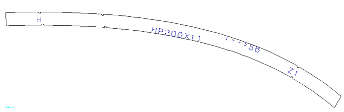
The end types, overlap mark and reference lines are marked with a small gap at the contour of the template. This mark is asymmetric to have no confusion, the longest side of the gap is mentioned as the measurement side.
The text of the template is not rescaled which means that in some cases the text will be overlapping each other.
End type can be marked as a slanted or perpendicular shaped to the shell. To define the perpendicular types, the environment can be set in %ROE_90_ENDTYPES%. In this environment the names of the end type, defined by the variable TY in the R line of the type file in your %NCGNORMS%/profs directory, must be set. A comma (,) must be used to specify the last mark of the name, for example: A,H,B,C,. If this environment is not set, all end types will be exported as slanted types, in some cases even if the type divination is perpendicular.