Creating profile sketches
You can select to create profile sketches when you create production information in the 3D-Contek or Shell application in Production > Production > Production Information.
To create profile sketches, select Sketches in the Create Production Information dialog.
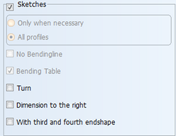
Only when necessary – Sketches are normally only generated for profiles which contain cutouts and/or (D/V) holes or when bending information is necessary.
If the logistical field Process_sketch is present in the logistical database you can set whether a sketch should be generated for a profile or not. This field can have one of the following values:
|
1 |
a profile sketch is not necessary |
|
2 |
a profile sketch is necessary |
|
3 |
a profile sketch is never necessary |
|
4 |
a profile sketch is always necessary |
The values 1 and 2 are automatically determined by the system after each modification to the profile, in case the profile has one of these values already defined. By including this field in a logistical data menu you can to override this automatically determined value. See Using a logistical data menu for information.
All profiles – Sketches are made of all the profiles within the selection. This is preselected when creating profile sketches for normal and small layouts. If the profile or shell frame itself has no attributes but an Outfitting hole is passing that part, this needs to be selected.
No Bendingline – This option is available only if Include bent profiles is selected in the dialog. When selected, the inverse bending line will be removed from the profile sketch.
Bending Table – This option is only available only if Include bent profiles is selected in the dialog. When selected, the bending height of the inverse bending line will be placed in a table instead of using the dimension arrows directly underneath the profile. The bending table is placed on the sketch in a specific drawing area. See Sketch Layout for more information.
Turn – The normal viewing direction of the profile on the sketch is from the molded side to the thickness side. By selecting this option you can turn the viewing direction so that the thickness side is on top.
Dimension to the right – When this option is selected, the dimensions will be placed on the right side of the indication, and the value are positioned starting from the right profile end point. When cleared, the dimensions will be placed on the left side of the indication, and the values are positioned starting from the left profile start point.
With third and fourth endshape – When this option is selected, the flange of the profile will be draw on top of the body of the profile, including the end types of the flange.
Note: To avoid distorted drawings, the system will lengthen the profile in the sketch if it is too short. The values and measurement will be according to the real profile length. Cutouts and holes will be positioned from the left start point of the profile.
You can influence the way in which the sketch will be created in System Management > Production > Profile Sketch > Settings.