Adding new equipment
In 3D-Contek you can select equipment from the CADMATIC Outfitting Component Modeller library and add it to the current view. New equipment is sent to the Hull Agent only when the drawing is saved (not when updating Outfitting).
Do the following:
-
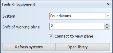
Select Tools > More Tools > Equipment. The Tools -> Equipment dialog opens.
Note: Always use Refresh systems when using this function for the first time in your project, in order to get the latest Outfitting systems. If this is not done, you will get an error message when saving the view. Refresh the systems also when systems are changed in Plant Modeller.
-
In the System field, select the system to which to add the equipment. The default selection is the system that was last used for the same block. If the list does not seem to be up to date, click Refresh systems.
-
If you want to place the model slightly in front of or behind the current view plane, use the Shift of working plane setting to specify the shift in depth. This is possible because the equipment model is placed with its origin in the view plane of the current view.
-
To make a topological connection with the added equipment to the view plane, select Connect to view plane. The system will use the plane level of the view as the origin point of the equipment, taking into account the possible offset defined as the shift of working plane. If the plane of the view changes because the view properties, reference surface, grid, or a related HiLTop parameter is changed, the equipment is repositioned to the new plane. This way, the connected equipment always follows the view plane.
Tip: You can disconnect the equipment and change the shift in working plane later in Tools > More Tools > Modify Equipment Connection.
-
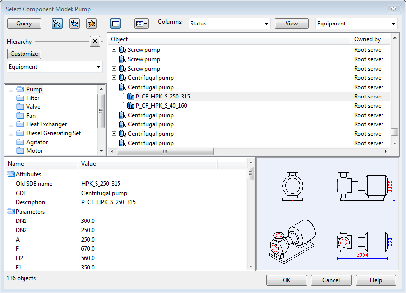
Click Open library. The Select Component Model dialog of CADMATIC Outfitting opens. This might take a little time, depending on the request check frequency defined for the Hull Agent.
-
Select the appropriate equipment, and then click OK to close the library. The selected equipment is placed in the current view.
-
Save the view. The equipment is sent to the Hull Agent and stored in the project. The parts are assigned a special pen color to indicate that you cannot manipulate them (move them, for example) until Outfitting data is updated. The pen used is defined in System Management > Projects > Outfitting > Equipment > Settings > Equipment Preliminary Pen Number.
The added equipment is still only a 2D preview. You can copy, shift, or remove the equipment in the same way as you would any other 2D items such as lines or circles. For example, you can right-click the view and select Manipulate > Interactive Move to drag the equipment to a different location.
If you copy and paste existing equipment and save the view, the parts will be handled in the same way as new parts added from the Component Modeller Library; the parts are assigned a pen color to indicate that the parts cannot be manipulated until Outfitting data is updated.