Comparing profiles in the profile sketch
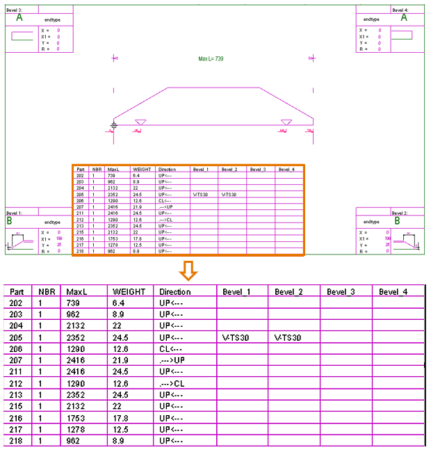
Multiple profiles can be compared in a single profile sketch. The profiles will be shown together in the profile sketch and the relevant differences will be summarized in a comparison table. This allows comparing similar profiles efficiently, and using a separate profile list sketch is no longer necessary.
The ncgrobot.ind file in the project norms must first be set up for the profile comparison. Once the ncgrobot.ind file has been set up, the comparison table will be included in the profile sketch when the Production > Create Production Information function is run with the Sketches option selected.
Notes:
-
The comparison table is shown only if multiple profiles meet the comparison criteria and more than one profile is valid for the comparison.
-
Profiles containing cutouts, holes or bending data are not valid for the comparison and will not be shown in the comparison table.
Setting up ncgrobot.ind for profile comparison
The comparison criteria, as well as the content and structure of the table, are defined in the ncgrobot.ind robot layout file in the project norms.
Two arguments and parameters for the arguments must be defined in the ncgrobot.ind file to enable profile comparison:
-
DATA_COMPARE! – The comparison criteria are defined with the parameters following the DATA_COMPARE! argument.
-
DATA_TABLE! – The content and structure of the comparison the parameters following the DATA_TABLE! argument.
Note: The DATA_COMPARE! and DATA_TABLE! arguments must be positioned after the F lines and before the CUTOUT statement in the ncgrobot.ind file.
DATA_COMPARE! argument
The DATA_COMPARE! argument must be followed by the comparison criteria, separated by commas. The comparison criteria parameters are logistical database fields prefixed with the $ character. They represent the properties of the profiles.
The last argument following the comparison criteria must be ,END.
 Show/hide example
DATA_COMPARE!$FIRST_TYPE,$FIRST_R1,$FIRST_R2,$FIRST_R3,$FIRST_R4,$FIRST_R5,$FIRST_R6,$FIRST_R7,$FIRST_R8,$FIRST_OL,$SECOND_TYPE,$SECOND_R1,$SECOND_R2,$SECOND_R3,$SECOND_R4,$SECOND_R5,$SECOND_R6,$SECOND_R7,$SECOND_R8,$SECOND_OL,$THIRD_TYPE,$THIRD_R1,$THIRD_R2,$THIRD_R3,$THIRD_R4,$THIRD_R5,$THIRD_R6,$THIRD_R7,$THIRD_R8,$FOURTH_TYPE,$FOURTH_R1,$FOURTH_R2,$FOURTH_R3,$FOURTH_R4,$FOURTH_R5,$FOURTH_R6,$FOURTH_R7,$FOURTH_R8,$CENTER_DISTANCE,END
See Appendix: Logistical database fields for a list and descriptions of logistical database fields.
DATA_TABLE! argument
The DATA_TABLE! argument must be preceded by a value which defines the maximum number of rows in the comparison table. Following the DATA_TABLE! argument, groups of three parameters define the columns in the table. Each column is defined in with the following three parameters:
-
The maximum number of characters in the column, followed by a colon.
-
The column header text (the text in the top row of the column), followed by a comma.
-
The logistical database field (prefixed with the $ character) whose value is filled in the cells of the column, followed by a comma.
Show/hide example
15,DATA_TABLE!3:Part,$POSNUMMER,3:NBR,$AANTAL,6:MaxL,$Length,6:WEIGHT,$Weight.32.8.1.0,9:Direction,$VANE_TEKEN,7:Bevel_1,$FIRST_B_TYPE$FIRST_B_1,7:Bevel_2,$SECOND_B_TYPE$SECOND_B_1,7:Bevel_3,$THIRD_B_TYPE$THIRD_B_1,7:Bevel_4,$FOURTH_B_TYPE$FOURTH_B_1
In the example, the maximum number of the rows in the table is 15. The first column contains a maximum of three characters, the header text for the column is "NBR", and each cell of the column under this header shows the part number of the profile.
Positioning of the comparison table in the sketch
The position of the comparison table in the profile sketch is determined in the profile sketch layout, in System Management Production > Profile Sketch > Sketch Layout.
The position of the comparison table is set with the User text 9 field.
The text properties set for User text 9 in the sketch layout determine the text size in the sketch.