Creating shell frames in longitudinal directions
It is possible to create a shell frame that runs along a longitudinal line, for instance along a knuckle line or a seam line. This can be done in the 3D-Show application or in the Shell application.
To create a shell frames in the 3D-Show application:
-
Open the 3D-Show or Shell application.
- In 3D-Show – Retrieve the block you want to create shell frames in by selecting Home > Drawing > Show > Show Active Block.
- In Shell – Open the drawing where you want to create shell frames in.
-
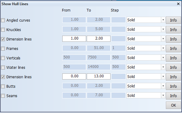
Select Home > General > Show Hull Lines, and then select the hull lines that you wish to use for creating the shell frames. Click OK.
The selected hull lines appear in the graphical window.
-
Select Construction > Insert > Shell Frames. Depending on the application, then select one of the following:
In 3D-Show, select from the orientation options:
- Fixed Angle to Shell – The Fixed Angle to Shell dialog opens.
- With Fixed Angle to Base – The Shell Frame with Fixed Angle to Base dialog opens.
- With Fixed Height – The Normal Shell Frame dialog opens.
- With Fixed Width – The Normal Shell Frame dialog opens.
- Cross Shell Frames – The Normal Shell Frame dialog opens.
In Shell, select Insert > in View. The Fixed Angle to Shell dialog opens.
Next you define the direction, the position and the type of the shell frame. The available options vary slightly depending on the chosen orientation.
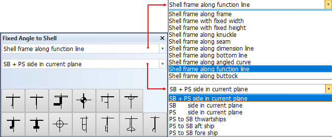
Below, the Fixed Angle to Shell dialog is used as an example. That dialog opens when you select Fixed Angle to Shell in the 3D-Show application, and in View in the Shell application.
-
Select the following:
- In the first drop-down menu, select the direction that you want the shell frame to run along.
- In the second drop-down menu, select the position of the shell frame.
- Select the type of shell frame.
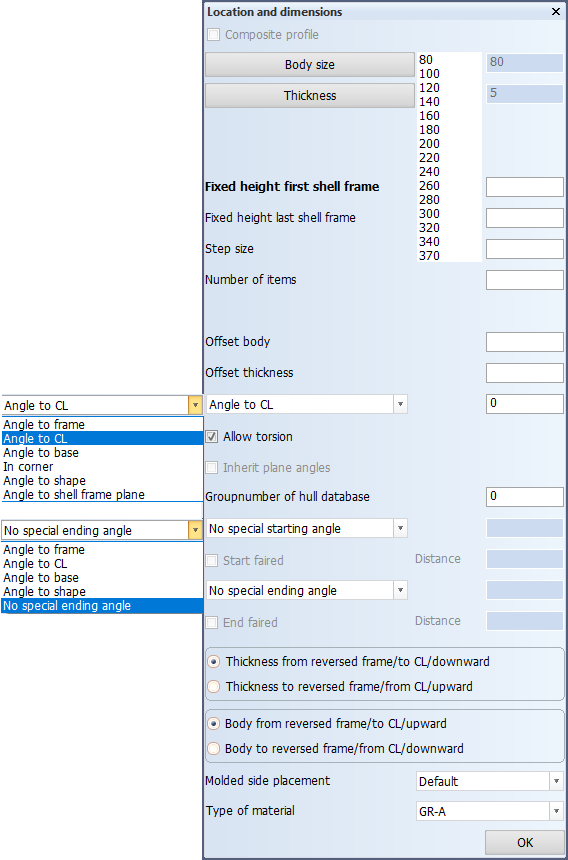
The Location and dimensions dialog opens. The previous dialog stays open in the meantime, and you can still change the previously defined settings while working in the Location and dimensions dialog. In case you change anything in the first dialog, the second dialog gets automatically updated. The image below shows the dialog that opens when selecting shell frames with fixed angle to shell.
-
Define the following properties for the shell frame:
Composite profile – By selecting this option you can code bodies and flanges for certain shell frame types separately, while the design system still treats the shell frame as one complete construction item. A shell frame like this is called a composite shell frame. Composite shell frames are like composite profiles, but H and I types are not available for shell frames. See Composite profiles for more information.
Body size and Thickness – Set the size and thickness for the body and the flange of the shell frame.
Fixed width first shell frame, Fixed width last shell frame, Step size, Number of items – These settings change depending on the direction you set in the first dialog box. You can define the position of the first shell frame and the last shell frame, the number of total shell frames, and their distribution by adding step size.
Offset body and Offset thickness – Define how much offset the shell frames should have from their relation.
The Angle definition drop-down menu – Each shell frame has it's own angle definition that you can set in the angle definition drop-down menu. Select what the angle should be measured to, and define the angle in degrees. See Creating shell frames in a corner for more information on how to create shell frames in corners.
Select the Allow torsion option to allow the torsion of the shell frame.
Note: It is not possible to indicate bending in multiple directions in production information for shell frames yet.
The Inherit plane angles option is only available when the shell frames are defined at dimension lines. These dimensions lines have in-plane definitions that the shell frame can inherit. If this option is selected, the in-plane definitions of the involved dimension lines are used when creating shell frames.
Properties of starting and ending angles – To define special starting andending angles for the shell frame, select the desired option from the drop-down menu, and define the angle in degrees. You can also set fairing by selecting the Start faired and End faired options.
Note: During the calculation of a shell frame, the start and end angles override the in-plane definition. In cases where the Inherit plane angles option is selected, and also start and/or end angles are defined, only the mid-section of the shell frame will use the in-plane definitions.
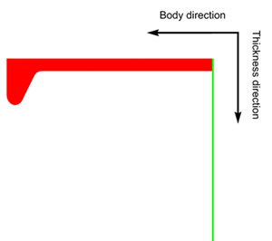
Thickness from/to and Body from/to directions – Set the body and thickness directions of the shell frame.
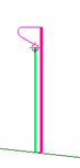
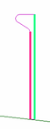
Molded side placement – This setting sets the molded side of the shell frame. By default a shell frame is placed by its molded side. It is possible that the shell frame is not aligned as desired with the construction item that is located on the other side of the plate, if both parts have the default thickness direction. This is because it is the molded lines of the parts that are aligned. By changing the molded side placement it is possible to change how the shell frame is aligned with the construction item that is located on the other side of the plate. The molded side position (red line in the left side picture below) can be changed from the default to the thickness side of the shell frame (full thickness or base width; red line in the right side picture below), or to the midpoint of the shell frame thickness or base width.
The available options are:
- Default – The shell frame is placed by its molded side.
- Center – Molded side is placed at the center of the shell frame body. Placement is by the midpoint of the shell frame thickness or base width.
- Base width – Molded side is placed on the thickness side. Placement by the thickness side (at full thickness or width).
See Molded side placement for shell frames for more information.
Type of material – Select the material type of the shell frame.
-
Click OK to confirm the properties of the shell frame. The Limitations and Endtypes dialog opens.
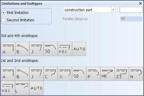
Define the first limitation of the shell frame by indicating a construction item, hull lines, yellow menu lines or add fixed values. It is also possible to define a parallel distance from the relation and to include a description.
Confirm the limitation by clicking the 1st or 2nd endshape. If you do not select the 3rd or 4th endshape, the default will be used.
The shell frame appears in the graphical window.
Chapter Create Shell Frames in the Structural Design User Training Tutorial shows a detailed example of creating shell frames in the 3D-Show application.