Creating shell frames in orthogonal directions
Shell frames in orthogonal directions run parallel to water lines, verticals, or frame lines. You can create such shell frames in the 3D-Contek application.
Note: You must have frame views for each shell frame you wish to create. To create new frame views, select Home > Create > Frame, and define the frame view properties in the Frame View dialog. You can determine how many frame views you wish to create in the No. of Sections box.
You can create a shell frame in one view, and copy that shell frame to all the other frame views by using the Copy 3D-Items function.
Creating shell frames
-
Select Construction > Shell Frames > Insert > in View in the 3D-Contek application.
-
Indicate a hull line or a plate you wish to position your shell frame on. The Create Shell Frame dialog opens.
-
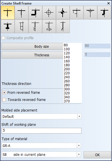
Define the following properties for the shell frame:
Shell frame types – Select the type of shell frame you wish to insert. Thumbnails show the structure of each available shell frame.
Composite profile – By selecting this option you can code bodies and flanges for certain shell frame types separately, while the design system still treats the shell frame as one complete construction item. A shell frame like this is called a composite shell frame. Composite shell frames are like composite profiles, but H and I types are not available for shell frames. See Composite profiles for more information.
Body size and Thickness – Set the size and thickness for the body and the flange of the shell frame.
Thickness direction – Set the thickness direction of the shell frame. The point of orientation for this setting can be the base, the reversed frame and the center line depending on the position of the shell frame.
Molded side placement – This setting sets the molded side of the shell frame. By default a shell frame is placed by its molded side. It is possible that the shell frame is not aligned as desired with the construction item that is located on the other side of the plate, if both parts have the default thickness direction. This is because it is the molded lines of the parts that are aligned. By changing the molded side placement it is possible to change how the shell frame is aligned with the construction item that is located on the other side of the plate. The molded side position (red line in the left side picture below) can be changed from the default to the thickness side of the shell frame (full thickness or base width; red line in the right side picture below), or to the midpoint of the shell frame thickness or base width.
The available options are:
- Default – The shell frame is placed by its molded side.
- Center – Molded side is placed at the center of the shell frame body. Placement is by the midpoint of the shell frame thickness or base width.
- Base width – Molded side is placed on the thickness side. Placement by the thickness side (at full thickness or width).
See Molded side placement for shell frames for more information.
Shift of working plane – Set values for the shift of working plane in this setting.
Type of material – Select the material type of the shell frame.
Position of Shell Frame – Select in the drop-down menu the position of the shell frame on the SB or PS side.
-
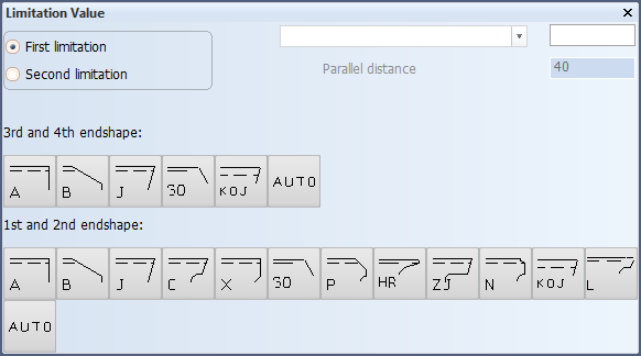
Click OK. The Limitation Value dialog opens.
-
Define the first limitation of the shell frame by indicating a construction item, hull lines, yellow menu lines or add fixed values. Confirm the limitation by selecting the 1st endshape. Optionally you can also select the 3rd endshape. If you do not select the 3rd endshape, the default will be used.
-
Define the second limitation by indicating a construction item, hull lines, yellow menu lines or add fixed values. Confirm by selecting the 2nd endshape. Optionally you can also select the 4th endshape. If you do not select the 4th endshape, the default will be used.
-
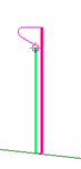
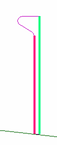
The shell frame appears in the graphical window.
Chapter Create Iceframes in the Structural Design User Training Tutorial shows a detailed example of creating shell frames in 3D-Contek.