Construction lines
In the shape definition section #vorm of the bracket type file it is possible to use straight construction lines to create more complex shapes.
A construction line establishes a new local straight orthogonal coordinate system which can be used to define a part of the bracket contour, especially the crossover part from one relation to the other.
Construction lines are defined in bracket type files, in sections where the axis variables U, V ,X and Y are defined (sections #as1, #as2, #as3 and #as4).
The syntax of the construction line definition is:
CL<line number> <x1 coordinate > <y1 coordinate> <x2 coordinate> < y2 coordinate>
Three construction lines can be defined (<line number> = 1,2,3). Two straight orthogonal coordinate systems are established for each defined construction line.
-
The first coordinate system is the local U system. The positive x-axis is directed from the starting point to the end point. The y-axis is directed orthogonally to the construction line away from the bracket's global origin. The starting point is used as the origin of the local coordinate system. Contour points relative to this coordinate system are defined in the usual way (AU1 U2 or CU3+U5 U3+U7). Because the coordinate system is straight, the function of A and C is the same. The definition line also places the length of the line in the corresponding U, V, X or Y variable.
-
The second coordinate system is the local V coordinate system. The positive x-axis is directed from the end point of the construction line towards the starting point. The positive y-axis is orthogonal to the construction line, and is directed away from the global origin. The end point is used as the origin of the local coordinate system. Contour points are defined as AV1 V2 or CV2+V4 V2+V5, for example.
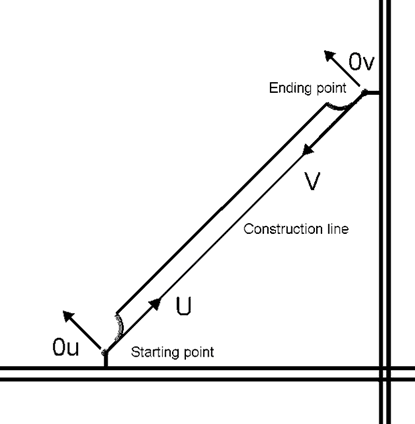
The origin of the first local coordinate system (U) is indicated by AU U or CU U which is the starting point of the line. The origin of the second system is AV V or CV V which is the end point.
A contour vector relative to these coordinate systems is defined by LC1, LC2 and LC3 lines or PC1, PC2 and PC3 points or CC1, CC2 and CC3 arcs.
See also L line, C line and P line for information on how to define a bracket contour.
The syntax for defining a vector is:
LC<line number> <x1 coordinate > <y1 coordinate> <x2 coordinate> < y2 coordinate>
Example:
LC1 AU U AU5+U6 U
The syntax for defining a point is:
PC<line number> <x1 coordinate > <y1 coordinate>
Example:
PC1 AU5+U3 U
To create an arc, a C line or an CC<line number> can be used. The syntax of the CC<line number> line is the same as for the normal C-line. Only when the centre point is defined with the C-line, the CC<line number> line must be used to define the centre point relative to the local coordinate systems.
Example:
CC1 AU1 U2 ?
Note: The last defined point relative to the normal coordinate system is the same as the starting point of the construction line. The end point is the same as the first defined point, relative to the normal system.
6 4
#as1
-1
R1
10.0
R3
25
20
#as2
R2+U4
U3
CL1 AU2+U4 U3 AV1 V2
U5
#vorm
L U;CU4 U AU2+U4 U
L AU2+U4 U AU2+U4 U3
LC1 AU U AU5+U6 U
CC1 ? ? U5
LC1 AU5+U6 U AU5+U6 U5
LC1 AU5+U6 U5 AV4+U6 V4
LC1 AV4+U6 V4 AV4+U6 V
CC1 ? ? U5
LC1 AV4+U6 V AV V
L AV1 V2 AV1 V
L AV1 V V;CU4 V
C V V U1*U4
P U;CU4 U
E
M D1 U;CU4 U AU2+U4 U
M D2 AV1 V V;CU4 V
Q
The functionality of A, C in AU1 U2 or CU1 U2 is the same in these local coordinate systems.
With function P, the contour point is found by intersecting a line parallel to the normal coordinate system and the construction line.
With function PU, a line parallel to the normal V-axis is used, while function PV results in the use of a line parallel to the normal U-axis.
In the above example the length of the construction line is placed in V3.