Displaying template markings
The user can mark the templates and the sight line plane on the DXF data of the shell plate. These marking lines can be used to position the templates during the bend process. The template markings consist of lines, symbols, and description. No thickness indication is added to the DXF data.
The preconditions of adding template markings to your DXF data are the following:
- You have successfully created templates for the shell plate. To learn how to create templates go to chapter Templates for shell plates.
- Production Information property is of the template set is set to Yes.
Note: In order to add marking for sight line plane to the shell plate as an addition to the template markings, make sure that the right settings are set in the System Management. The setting for Production > Plate Cutting Data > Shell Plates > Marking > Sight Line Presentation must be set to a value other than off or uit.
You can add the following template markings to the plate cutting data of the shell plate:
- marking lines that show the template's position
- marking text that identifies the templates
- symbols that help positioning the templates on the shell plate
- marking line that shows the sight line plane on the shell plate
- symbols that help positioning the sight line plane template on the shell plate.
Go to Production > Plate Cutting Data > Shell Plates > Marking in the System Management application to read more about these settings.
The image below shows the template marking symbol threshold marked by red circles and the sight line marking offset marked by green arrows.
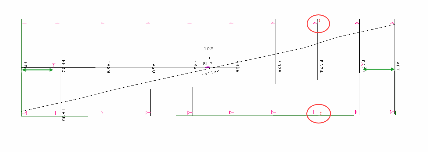
The symbol(s) on the shell plate matches the symbol(s) marked on the templates allowing correct positioning of the templates on the shell plate during construction. To read more about the matching symbols on the templates go to chapter Including shell plate marking symbols.