Including shell plate marking symbols
The purpose of adding shell plate marking symbols to the coded templates is to provide information on how to place the templates on the shell plate during production. Matching template marking symbols can be added to the shell plate. Positioning the templates so that the marking symbols match ensure correct placement.
The following special symbols can be marked on the template DXF:
-
All symbols that can be defined in System Management > Production > Plate Cutting Data > Shell Plates > Marking.
-
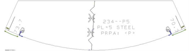
Two symbols used for positioning the templates on the shell plate. These are placed at a specified distance measured along the template contour that touches the shell plate. The default value of this distance is 100 mm and it can be changed in System Management > Production > Plate Cutting Data > Shell Plates > Marking > Template Marking Symbol Offset.
The green arrows show the distance on the template in the image below. The blue marks show the orientation of the symbols.
If the length of the curved part of the template is equal or smaller than the System Management > Production > Plate Cutting Data > Shell Plates > Marking > Template Marking Symbol Threshold setting, only one symbol will be placed on the template, located halfway on the contour.
It is possible to use the same template set for shell plates that are mirrored over the center line, as the system mirrors the marking symbols also on the template.
-
A special symbol marking the intersection of the coded template and the sight line plane.
-
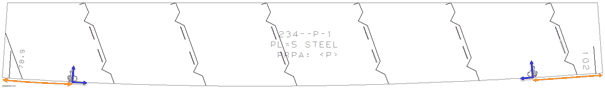
There are symbols on the coded sight line plane as well that help in the positioning the template on the shell plate. These define the distance between two symbols on the sight line plane template. The settings for these symbols are the following:
- System Management > Production > Plate Cutting Data > Shell Plates > Marking > S. L. Marking Symbol Threshold
- System Management > Production > Plate Cutting Data > Shell Plates > Marking > S. L. Marking Symbol Offset
The image below shows the distance and the orientation of these symbols.
-
There are symbols that show the angle between the template and the shell plate. The settings for these symbols are the following:
System Management > Production > Plate Cutting Data > Marking > Angle of Connecting Parts
System Management > Production > Plate Cutting Data > Shell Plates > Marking
See Displaying template markings for more information about the matching template marking symbols that are placed for on the shell plate for correct positioning.