Adding bevels manually to the shell plate contour
Shell plates can receive bevels automatically if their properties match with one of the rules set in System Management > Construction > Welds/ Bevels > Plate Bevel Rules.
You can add bevels manually to the shell plates by using the Construction > Insert > Single Bevel function of the Shell application. Below it is described how to add single bevels on the shell plate. For information on modify these bevels, see Modifying bevels.
-
Open the Shell application and load a drawing that also contains shell plates.
-
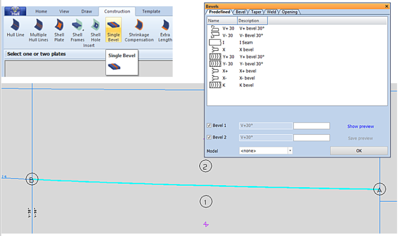
Select Construction > Insert > Single Bevel.
-
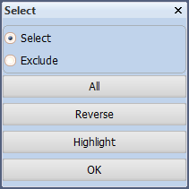
The system will ask you to indicate one or two plates in the graphical window, while displaying the Select dialog. Indicate the plate(s), and click OK.
-
Define the bevel properties in the Bevels dialog box. See Bevel properties for predefined bevels for information on how to adjust the bevel properties.
-
Specify bevel attributes in the same dialog box. Note that a bevel is an attribute that belongs both to the shell plate and to the involved relation, just like in the case of bevels on a regular plate created in the 3D-Contek application. The edge type is defined as edge to a plate in plan view. The position of the bevel is halfway to the relation it belongs to.
-
Click Show preview to see your attribute changes. Click OK to save the bevels on the shell plate. The bevel symbols appear at the relevant contours of the shell plate.
Note: This function is not available in 3D aft or 3D forward views.