Selecting parts for adding weld lines
It is possible to add weld lines manually with the function Construction > Welds > Insert > Insert.
When you select parts that are positioned near each other, no checks are made. Therefore, make sure you only select parts which are suitable for weld lines.
To select the parts for adding weld lines:
-
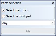
Select the main part. You can select any part in the drawn block except for the shell plates. The part you select is highlighted, and the selection in the Parts selection dialog automatically switches to Select second part.
-
Select the second part. You can also select a shell plate or a part from a dashed block. If you select any part without logistical information, such as a hole, corner hole, cutout without lugs, flange or welded seam, its main part will be treated as having been selected.
You can also manually switch between the main part and the second part options.
At switching, the previously selected part for that option is highlighted again. If you have not selected the main part before you select the second part, the system activates the Select main part option. The main part and the second part can be the same.
- Any
- Part in plan view
- Profile in plan view
- Bracket in plan view
- Part in section
- Profile in cross-section
- Flange or face plate
- Holes
- Cutouts and lugs
- Corner holes
- Welded seam
-
Click OK. Next, you need to select the weld line. See Defining weld lines on selected parts.
The drop-down menu includes the type of constructions which can be selected:
OK is disabled until you have selected both the main and the second parts.