Weld line splitting process
A weld line in the drawing can be split using the following steps:
- Indicate the weld line to be split.
- Indicate the starting point of the new weld line segment [optional].
- Indicate the ending point of the new weld line segment or type in a length value [optional].
Choosing a weld line to split but not choosing a new start or end point will result in a weld line replacing the existing weld line while containing the same properties.
Choosing the start of the existing weld line but ending the new weld line segment part way through will create a new weld line between the selected points, and a second new weld line to replace the remainder of the previous weld line.
Choosing a start and an end point which are not on either the start or the end of the initial weld line will remove the original weld line, and replace it with three new welds lines: One the user specified, and one from each of the chosen points until an end of the initial weld. However, if the distance to the end is less than the Split threshold specified in the configuration file, then the new weld line will automatically extend to the previous weld line end instead of creating an additional weld line shorter than the threshold value.
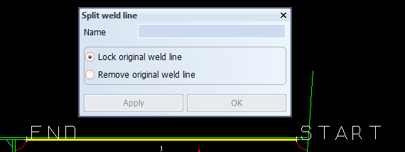
Indicate the weld line to split
All of the visible weld lines in the displayed blocks can be selected.
The selected weld line is highlighted and its actual start and end points are marked in the view. In the function panel, some information about selected weld line is shown to help the user to identify the weld line easier. By using the FDO <6> - Reselect, the user can repeat indicating a weld line, in case the wrong weld line was selected initially.
Indicating the start point
The start point can be indicated using mouse cursor, Snap keys or by entering coordinates in the Dynamic Input.
By using the <Enter> key, the closest weld line end point to the cursor is selected by the system as the starting point.
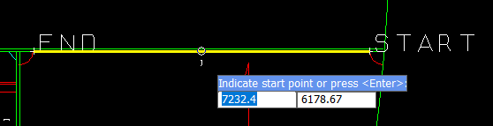
The indicated starting point can be changed in the 3D environment using the FDO <7> - Shift Start Point.
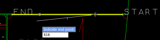
Indicating the end point
The end point can be indicated by:
- using mouse cursor to select a point graphically
- using Snap keys
- entering a distance relative to the start point calculated in the 3D environment along the weld line using the Dynamic Input or entering the coordinate of the desired end point. The option to switch between Length or Coordinate entry of an end point is done by pressing FDO <6>
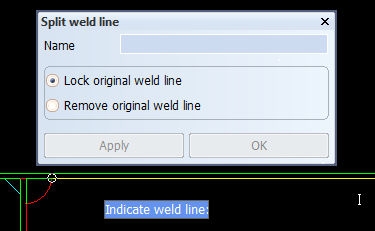
The Split weld line dialog
The Split weld line panel displays the name of the selected weld to help the user ensure that they have selected the correct weld line.
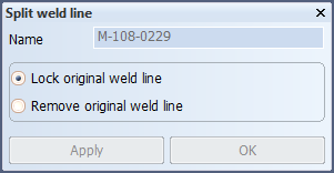
Behavior of the original weld line
A radio button is included in the panel of the splitting weld lines function to determine the behavior of the original weld line. This allows the user the choice to Lock the original weld line or Remove the original weld line. Locking the original weld line will keep the weld line in the weld database but it will not present it in the view, while instead presenting the new weld lines after splitting. The locked weld line will still be listed in the Weld Manager tool within Hull Viewer as locked to ensure traceability of the weld lines. The option to remove the original weld line will take the original weld line out of the system completely and leave only the new weld lines after the splitting process.
Apply
When the Apply button is clicked:
- user input is checked and validated then either:
- an error message is shown for invalid user input
- the following occurs when the user input is valid:
- the original weld line is locked
- one, two or three new weld lines are created, depending on the locations of the start and end points
- the weld lines in the drawing are updated according to the latest changes
- function panel remains open.
OK
The OK button performs the same actions as Apply, except the function panel is closed as well.
Weld labels
The weld labels belonging to the split weld line remain unchanged until a manual drawing update.