Standard profiles endcut welding
In order for the weld lines on profile endcuts to be calculated, the project must meet the following conditions:
- The type files describing the endcuts must contain the weld keywords, found under Endcut type file, specifying the parts of the end cut that should receive weld lines
- The project must include Weld side rules to determine where the weld lines should be placed upon the profile
The prerequisites for the profile endcut welding lines are:
- The profile endcut should make contact with another part.
- It should have a predefined bevel assigned, see Profile beveling rules.
- It should be assigned a profile end shape type with defined weld information.
Endcut welds are divided into two types: body welds and flange welds. These two types are calculated separately by intersecting the body faces and flange faces of the profile with the endcut solid separately.
Parallel segments to these are calculated according to the profile thickness and flange thickness. This is done to have segments on the molded and thickness sides and halfway between the two, for the weld connection associated with WELD_SIDE_MIDDLE.
The resulting faces are intersected with the endcuts. The weld position (molded / thickness / middle) is maintained during this process. Intersection of faces and solids will result in a collection of edges. These edges are connected to form the final weld lines. During this connection, the required vectors for the weld information are calculated using the underlying faces (of the body / flange and endcuts).
Endcut type file
The WB / WF / WA keywords can be used in the profile endcut type files. One of these keywords can be appended to any line describing the endcut geometry (L or C lines). Inserting 'WB' (Weld Body) means that segment of the endcut should be welded if the type is applied to a profile body (1st or 2nd endcut). Adding 'WF' (Weld Flange) indicates the same in case the end type is applied to the profile flange (3rd or 4th endcut). If the segment of the endcut should have a weld line regardless of whether it is used as a body or flange endcut, the keyword 'WA' (Weld All) should be used. More information of type file definitions can be found in The type file.
For example, consider the following endcut definition:
P VC*V1 0
C 0 0 R4*V1
L 0 0 R1*VB VB
L R1*VB VB R1*VB-V3 H1
E R1*VB-V3 V2*H1 R1*VB 0
Graphically, this will look like:
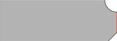
Suppose the nose, marked in red, should be welded in a case where the type is used as a body endcut. The type file should be modified to:
P VC*V1 0
C 0 0 R4*V1
L 0 0 R1*VB VB WB
L R1*VB VB R1*VB-V3 H1
E R1*VB-V3 V2*H1 R1*VB 0
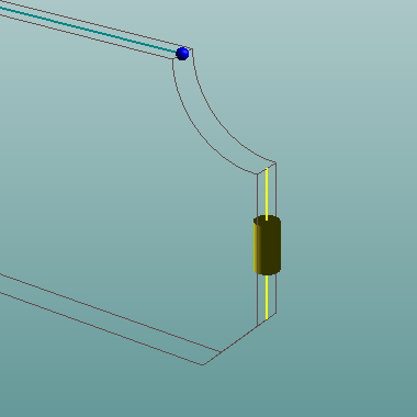
Resulting in a weldline on the nose of the profile endcut:
Specifying weld lines for consecutive segments in an endcut type file will result in a continuous weld line. However, body weld lines will not be connected to flange weld lines.
The side of the profile body or flange where the weld line appears depends on the regular Weld side rules.
For welds on the profile flange, the same steps should be followed as in the example above except with 'WF' instead of 'WB'. If welds are required on both the profile body and flange when this endcut is used, 'WA' should be used instead.
Pillar endcut welding
The procedure to add weld lines to the endcuts of pillars is the same as the procedure for standard profile endcut welding.