Weld lines on user-defined profile end shapes
A user defined profile can have any desired shape. This is why the system cannot precisely detect the body versus the flange, or the molded versus thickness side of the profile. Therefore, a manually created user definition of these weld lines on the endcut are needed to make a good connection between the end weld types and the user defined profile.
The definition of the weld lines in the type file should be added after the end, marked with an 'E-Line', of the header with the cross section description.
These weld lines can exist of lines, arcs and points. The elements do not need to be connected to each other. However, the shape definition should not begin or end with an arc segment so a point should be applied either before or after to prevent that situation. The keywords for weld lines on the user defined profiles are defined in the rule files by three letters followed by coordinates. The letters each have an important meaning:
- The first letter of the line represents the shape of the weld line itself and determines what information follows the keyword:
- L - Line segment, which will have two points in 2D coordinates following the keyword
- C - Arc segment, which will have the 2D coordinates of the centre of the arc and the radius value following the keyword
- P - Point, which will have one set of 2D coordinates after the keyword
- E - End of the body weld lines and will not have any coordinates following the keyword
- The second letter indicates the part of the profile where the weld line is being defined:
- B - Body of the profile
- F - Flange of the profile
- The third letter indicates which side of the profile the weld line is being applied to:
- M - Molded side
- T - Thickness side
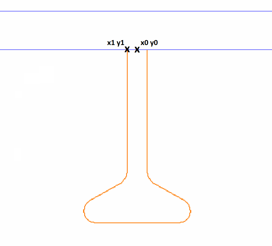
The following profile shape will be used in an example for defining weld lines in the type file:
![]()
This example will discuss applying the weld lines on the molded side of the body. The process is very similar for the thickness side or on the flange. The first line will create a weld line from x0 y0 to x1 y1, representing two 2D points, as seen in the figure below:
This is done by adding the following line in the type file:
LBM x0 y0 x1 y1
These lines can use numeric or variable input, or even an expression, so x0 could be given a value earlier than this line, x0 could be replaced in this line with the value of the point in the x-direction or even with an expression such as b1*v1-5.
The second step will be to create a line from x1 y1 along the molded side of the body to the start of the first curve on the profile, at x2 y2. The previously created weld line is shown in green on the profile as well:
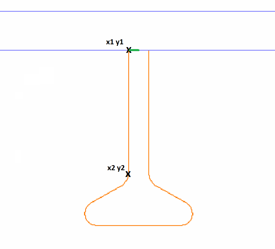
This weld line is created by using the following line:
LBM x1 y1 x2 y2
The next step will follow the curve in the profile immediately after x2 y2. This location is shown in the figure below:
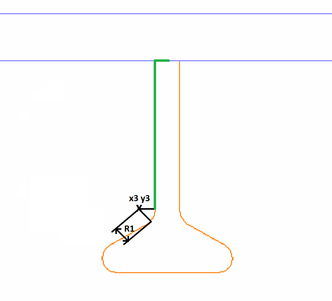
The point x3 y3 is the centre of the arc and is not actually on the profile itself. R1 represents the radius of the arc. This section is added using the line:
CBM x3 y3 R1
The straight section between the two arcs will be covered next:
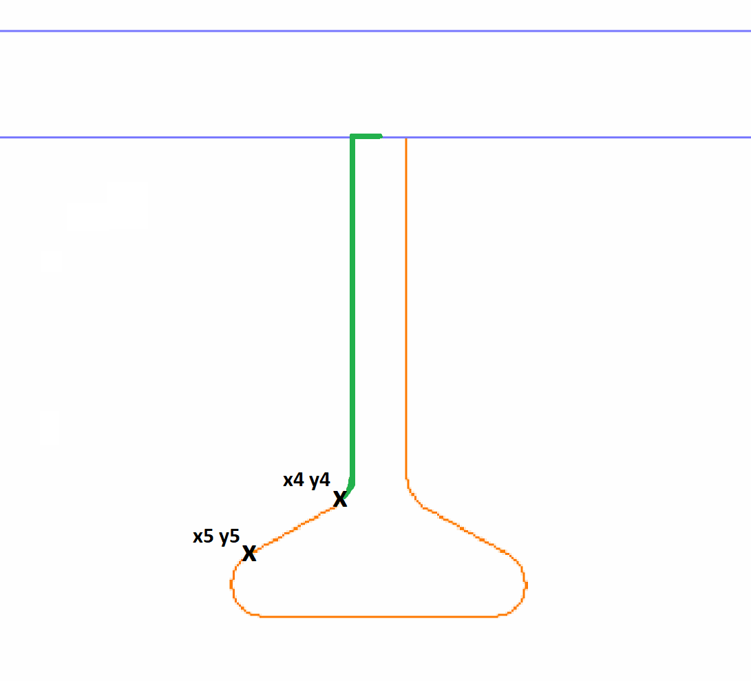
The weld line connecting x4 y4 and x5 y5 is defined with the line:
LBM x4 y4 x5 y5
The curve after x5 y5 is defined next using the information shown here:
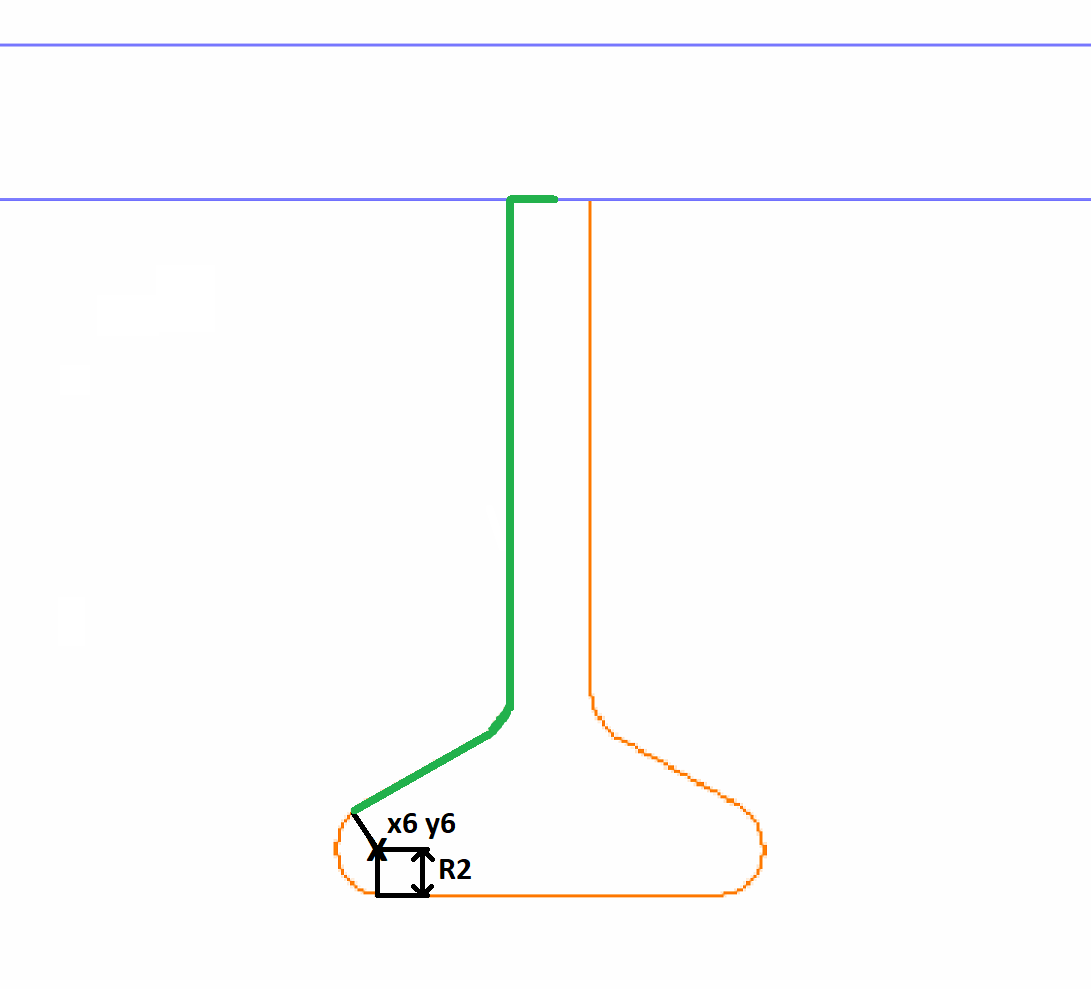
This weld line arc is defined using the following line:
CBM x6 y6 R2
For this example, the remainder of the user defined profile will be treated as a flange. However, since a definition should not end with an arc, a point should be applied at the end of the arc before the E line. So, then two lines consisting of:
PBM x7 y7
EBM
Must be added
The flange weld line definition for the molded side of the user defined profile covers from the end of the curve to the centre of the profile:
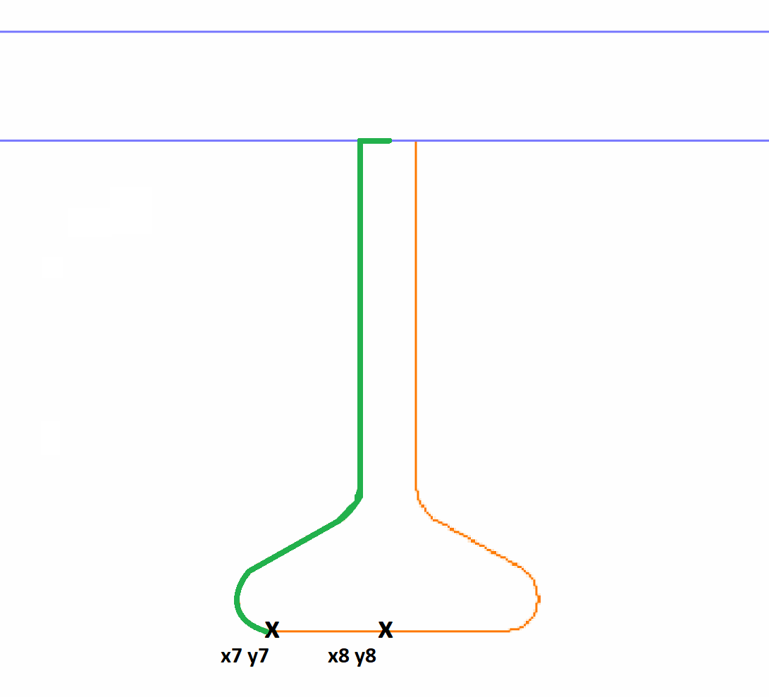
This is done using the line:
LFM x7 y7 x8 y8
The next image shows the total shape of the weld lines which have been defined on the body on the molded side of the profile:
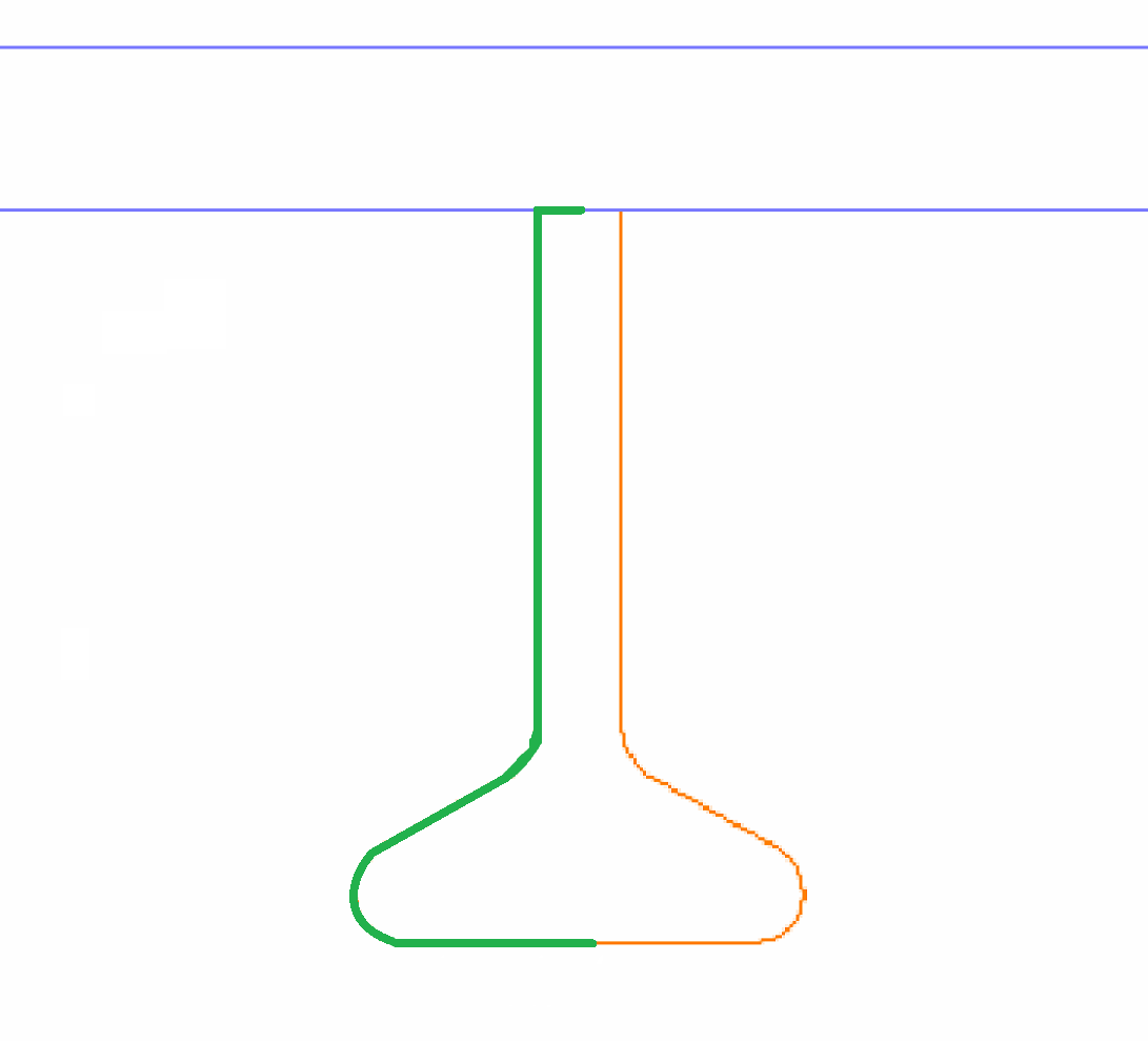
This means that the weld line definition for the molded side on the flange needs to be completed by using the final line:
EFM
The complete example definition for the weld lines on the molded side of the body of the user defined profile within the type file is:
LBM x0 y0 x1 y1
LBM x1 y1 x2 y2
CBM x3 y3 R1
LBM x4 y4 x5 y5
CBM x6 y6 R2
PBM x7 y7
EBM
LFM x7 y7 x8 y8
EFM
All of the lines on the molded side need to be defined in such a way that the material is positioned to the right side of these lines. The lines on the thickness side should be parallel to the lines on the molded side as much as possible. In order to define the weld lines for the thickness side, this above example should be repeated in the type file except that the M should be replaced by a T in each line.
An example of defining the same profile shape in a type file is given below to illustrate the use of numeric and variable input, and expressions:
LBM V1*VA 0 0 0
LBM 0 0 0 H1-VE-VF
CBM V9*VG H1-VE-VF V9
LBM VA*V9+V1 H1-VH-VF VA*V9-V7 H1-VH
CBM V9-V7 H1-V9 VG*V9
PBM VB VC
EBM
LFM V9-V7 H1 V1*VA H1
EFM
LBT V1*VA 0 V1 0
LBT V1 0 0 H1-VE-VF
CBT V1+V9 H1-VE-VF VG*V9
LBT VA*V9+V1 H1-VH-VF VG*VA*V9+V8 H1-VH
CBT V8-V9 H1-V9 V9
PBT VD V5
EBT
LFT V8-V9 H1 V1*VA H1
EFT
Shape definition describes how the lines, arcs and points are defined within the type files further.
For arcs the ! or ? can be used in a similar way as is done for the existing C lines, see C line.
User definitions can also be made for standard profiles if more customization is desired.