W line in the bracket type file
The predefined bevels that are to be applied on a bracket and/or a related part are defined in the W line in the bracket type file. The system cannot define the predefined bevels to be used and the associated weld lines if the W line is not present in the type file.
A specified predefined bevel can be applied (as a bevel attribute) at a specific contour segment of the bracket and at a specific relation of the bracket. By default the bevel is applied along the entire length of the relation. In case bevel information should only be applied to part of a relation, specific bracket relation keywords must be used to define the desired part. See Defining bevels on bracket relation segments.
The W line must be placed after the last M line in the type file.
See also Bracket type file.
Syntax of the W line
A W line begins with character W. It must always contain eight number values.
W 1 2 3 4 5 6 7 8
Each value is a predefined bevel number, as defined in System Management > Construction > Welds/Bevels > Predefined Bevels.
The first four values define the bracket contour segment on which the bevel is to be placed, so that the 1st value defines the bevel to be placed on the contour segment at the first relation, the 2nd value the contour segment at the second relation, and so on.
The last four values define the related part on which the bevel is to be placed, so that the 5th value defines the first related part, the 6th value the second related part, and so on.
- 1st value – The number of the predefined bevel on the bracket contour along the first relation
- 2nd value – The number of the predefined bevel on the bracket contour along the second relation
- 3rd value – The number of the predefined bevel on the bracket contour along the third relation
- 4th value – The number of the predefined bevel on the bracket contour along the fourth relation
- 5th value – The number of the predefined bevel on the contour of the part that is the first relation of the bracket
- 6th value – The number of the predefined bevel on the contour of the part that is the second relation of the bracket
- 7th value – The number of the predefined bevel on the contour of the part that is the third relation of the bracket
- 8th value – The number of the predefined bevel on the contour of the part that is the fourth relation of the bracket
Note: If a certain relation is not defined for the bracket, the corresponding number value must be set to zero.
Examples
Example 1
In this example, the bracket has two relations. Therefore a predefined bevel number can be defined for the 1st, 2nd, 5th and 6th values. We are not defining the 6th value here because we do not want a bevel on the contour of the second related part.
Because the third and fourth relations are not defined, the 3rd and 4th values (for the bracket contour segment) and the 7th and 8th values (for the contour of the related part) must be set to zero.
W 3 2 0 0 3 0 0 0
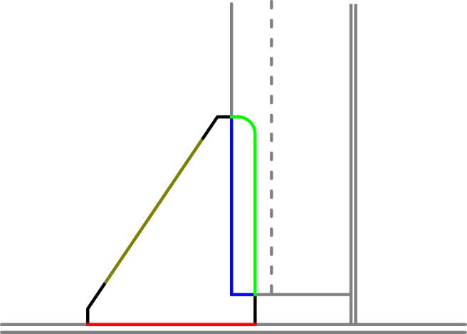
The result of this W line is as follows:
- The bracket and the related part will both have predefined bevel number 3 applied along the length of the red line (on the first relation).
- The bracket will have predefined bevel number 2 applied along the length of the green line, but on the related part (second relation).
- Neither the bracket nor the related part will have a predefined bevel applied along the length of either the orange or blue lines (on the third and fourth relations).
Example 2
The bracket shown below has three relations: first, second and fourth.
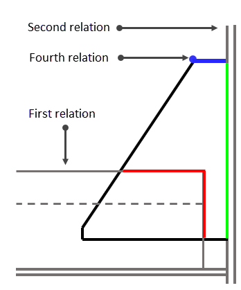
To have a bevel on the bracket contour segment along the fourth relation, (a profile in cross section, shown in blue), a predefined bevel number should be defined as the 4th value in the W line.
W 32 0 3 0 0 0 0
Note that in this case the 8th value must be set to zero, because the fourth relation is a profile in cross section where a bevel cannot be placed. A bevel could be placed here if the profile was in plan view (like the first relation).