Defining bevels on bracket relation segments
A bracket can have up to four relations. The bracket can touch or even overlap with the related parts as shown in an example below:
The parts of the bracket contour which should receive bevel information can be specified in the type file by defining the predefined bevel to be used per location. The W line in the bracket type file is used to specify which predefined bevel should be applied to a segment of the bracket contour, on either the bracket or the related part. By default, the bevel is applied along the entire relation.
In case bevel information should only be applied to part of a relation, then bracket relation keywords must be used.
Bracket relation keywords
Bracket relation keywords specify sections of the bracket contour to be beveled. These keywords are added after the geometric definitions on the relevant L line or C line in the bracket type file. The keywords are as follows:
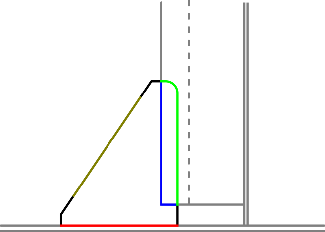
- BRR1 – First relation on the bracket (red line in the image above)
- BRR2 – Second relation on the bracket (green)
- BRR3 – Third relation on the bracket (brown)
- BRR4 – Fourth relation on the bracket (blue)
The first and second relations originate from the contour of the bracket. The third and fourth relations originate from the shape of the related parts. If two relations are on the same side of a bracket, they must be either the first and third or second and fourth relations. For example, the first and fourth relations cannot be on the same side of a bracket.
A bracket relation keyword specifies that the bevel should be handled as a bevel attribute instead of a predefined bevel. The bevel will still take the properties of the predefined bevel, but it can be modified by the user. Bevel information is applied along those geometric definitions to which the keywords are appended. It is still required to use the W-Line in the type file to specify predefined bevel numbers.
Bevels and weld lines
The bevels and weld lines on the related parts are determined from the last four digits in the W-Line in the bracket type file. The entire overlapped edge of the related part will be beveled / welded. The weld line is added automatically if the bracket and the related part touch each other (i.e. there is no gap; their distance is zero). It is not necessary to use the bracket relation keywords in this case. However, the bracket relation keywords must be applied to the bracket relation that is overlapped if there is a gap between the bracket and the related part. This is to force a weld line between the parts.
After inserting a bracket relation keyword, offset values can also be specified when the length of the bevel to be applied is different than the entire bevel contour along that specific relation. For an example, please refer to Bevels on bracket contour (bevel attributes).
The bevel and welding information on the bracket contour at the position of a faceplate, shell frame or profile baseline is generated automatically as a result of the Predefined Bevels placed by the Bevel Generator. The bracket type file will not override this process, as the predefined bevel determined within the Profile beveling rules takes priority.
Bevels and weld lines for brackets related to shell plates
If the contour of a bracket related to a shell plate streches over two or more shell plates or to a hull line, the system creates a bevel and a weld line automatically only on the bracket segment that goes along the related shell plate's contour. This is done according to the W line in the bracket type file. If other weld lines are needed for the bracket, they must be placed manually.