Definition point commands
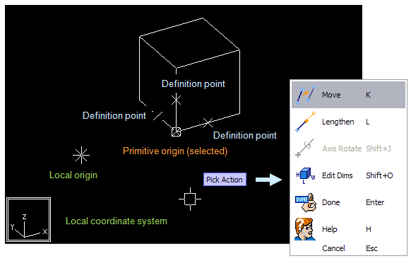
When creating or modifying a Primitive or Shape, you can see its definition points as small crosses. Use the definition points to shape and position the object as required. For example, you can rotate a box primitive around its origin point, or change the length of a beam primitive by adjusting one of its endpoints.
At any given time, one definition point is the active point, indicated by a rectangle around the cross. Primitive and shape commands always target the active definition point. Click another definition point to make that point active.
Definition points that no primitive or 3D shape is using are automatically removed.
When modifying a definition point using a command that prompts you to define a location, direction, distance, or radius, the context menu includes the commands described below.
Define location
You can use the following commands to define a location:
-
Create (Space) – Create a new definition point at the digitized 3D point.
-
Select by Name (N) – Select an existing point by name. This tool also shows the definition of the points.
-
Refer (P) – Connect to an existing point and obtain information from that point.
-
Relative Point (I) – Create a point located in a certain direction and distance from the definition point nearest to the digitized 3D point.
-
Parameterize (O) – Enter the coordinates (which can be parameterized) of the point in the local coordinate system.
Note: Do not use keyboard shortcuts Space and Q with parameterized components.
Define direction
You can use the following commands to define a direction:
-
Def. Dir – Define a direction from the digitized 3D direction using the commands in this menu.
-
Select by Name (N) – Define the direction by selecting a named target point.
-
GDL P1 --> P2 (P) – Define the direction by picking two 3D points.
-
Parameterize (O) – Define the direction by entering the coordinates (which can be parameterized) of the target point in the local coordinate system.
Define distance
You can use the following commands to define a distance:
-
As Digitized (Space) – Use the digitized value.
-
Enter Value (I) – Define the distance by entering a numeric value.
-
Define (O) – Define the distance by entering a parameterized expression.
-
P1 --> P2 (M) – Define the distance by picking two 3D points.
Define radius
You can use the following commands to define a radius:
-
As Digitized (Space) – Use the digitized value.
-
Pick (P) – Define the radius by picking its expression from a primitive in the active GDL. Make sure the 3D hit box is closest to the end point whose radius you want to use.
-
Measure (M) – Define the radius by picking two 3D points.
-
Enter Value (I) – Define the radius by entering a numeric value.
-
Define (O) – Define the radius by entering a parameterized expression.
Defining angle
You can use the following methods to define an angle:
-
As Digitized (Space) – Use the digitized value.
-
Enter Value (I) – Define the angle by entering a numeric value (in degrees).
-
Define (O) – Define the angle by entering a parameterized expression.
-
Measure (M) – Define the angle by measuring the angle between two direction vectors you are prompted to pick from the model.
Note: Angle values must be entered in degrees. Older versions of Plant Modeller required parametric definitions to be in radians.