Insert

On the Weld tab, the Insert group includes commands for inserting welds, either by manually tracing the weld path in the model or by using automated insertion that generates the weld path along the contour of one object touching or penetrating another. The weld path forms the visual 3D representation of the weld, using a 3D polyline composed of line and arc segments modeled with small-radius cylinders and tori. When completing the insertion, the program runs a data extraction utility that embeds data for the welded parts in the weld object. This allows properties of the welded parts to be listed together with the properties of the weld object in weld reports. Just be aware that if the welded parts are modified later, the embedded part information may no longer match the model. If the weld List is open, it is temporarily hidden for the duration of the insertion, and then reappears to show the inserted weld.
Insert weld
You can insert welds by defining a custom weld path in the model. After selecting the starting point, you can either insert one circular weld or define a weld path freely by adding straight segments, arc segments, and gaps.
Prerequisites
-
The project administrator has defined Welds settings for the project.
Do the following:
-
Select the Active logistics space, weld group, and weld system.
-
Select Weld tab > Insert group > Insert > Insert weld.
-
Select the object to be welded, and press Enter.
-
Select the object to which the first object will be welded, and press Enter.
-
Pick a point to designate the start point of the weld path. If inserting a circle, this point is its origin.
-
Define the weld path by adding the required segments:
-
Circle: To add a circular segment using the start point as the circle's center, select Insert circle from the context menu, define the circle normal, and enter a value for the circle diameter.
(A circle automatically completes the weld path; no new segments can be added afterward.)
-
Straight segment: To add a straight weld segment starting from the previously defined weld point, pick the end point of the new segment.
-
Arc segment: To add an arc-shaped segment starting from the previously defined weld point, select Insert arc from the context menu, pick the end point of the arc, and then pick the midpoint.
-
Gap: To add a non-welded gap to the weld path, select Insert gap from the context menu, and pick the point where the weld starts again. Gaps are visualized as dashed lines.
-
-
To complete the weld path, press Enter.
Weld beam
You can generate a weld path at the end of a beam that is in contact with the planar face of another object. If there is more than one potential target face, the weld is created for the one hit by a ray shot from the local origin of the beam profile.
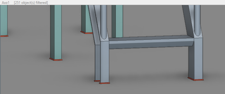
The program obtains the weld path by cutting the beam end with a face retrieved from the target object closest to the beam end and tracing this line. In an ideal case, this trace line follows the complete perimeter of the beam profile along the plane. However, if the beam end is sniped or mitered, the trace line only follows the part that touches the target face. The trace line is also trimmed by the boundary and any holes present on the target face. A Welds setting specifies the maximum offset from the weld path to the target face, and if this offset is exceeded at some point, a gap is inserted into the weld path to cover the part that is too far from the target face.
The weld is not created if neither object belongs to the logistics 3D space of the active weld group; if the target object is part of the same structural unit as the beam; if the beam end is in contact with a side face; or, if there is already a weld between the objects.
If this function cannot find the correct target object, use Weld touching objects instead to pick the target manually.
Prerequisites
-
The project administrator has defined Welds settings for the project.
Do the following:
- Select the Active logistics space, weld group, and weld system.
-
Select Weld tab > Insert group > Insert > Weld beam.
-
Select the beam by picking near the end that touches the other object, and press Enter.
Weld plate
You can generate a weld path along the front or back of a plate that is in contact with the face of another object. If there is more than one potential target face, the weld is created for only one of them.
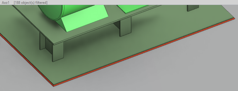
The plate part's object type can be Equipment, Structural, or Standard Component. You can also select objects with GDL models by selecting the 3D primitive (Plate, Sweep, Box) under the cursor. The program generates the weld path as a section curve of the selected primitive on the plane of the other object.
The program obtains the weld path from the boundary curve of the plate part. In an ideal case, this trace line follows the complete perimeter of the plate along the plane. The trace line is also trimmed by the boundary and any holes present on the target face. A Welds setting specifies the maximum offset from the weld path to the target face, and if this offset is exceeded at some point, a gap is inserted into the weld path to cover the part that is too far from the target face. This may occur if the plate is slightly misaligned with the target face.
The weld is not created if neither object belongs to the logistics 3D space of the active weld group; if the target object is part of the same structural unit as the plate; if the plate is in contact with a side face; or, if there is already a weld between the objects.
If this function cannot find the correct target object, use Weld touching objects instead to pick the target manually.
Prerequisites
-
The project administrator has defined Welds settings for the project.
Do the following:
- Select the Active logistics space, weld group, and weld system.
-
Select Weld tab > Insert group > Insert > Weld plate.
-
Select the plate, and press Enter. If the plate part consists of more than one geometric primitive, pick the object so that the cursor hits the plate primitive you want to weld.
Weld touching objects
You can generate a weld path along the seam where one object is in contact with another at a planar face.
The program obtains the weld path by cutting the first object with the face of the second object. The weld path is trimmed by the boundary and any holes present on the target face. A Welds setting specifies the maximum offset from the weld path to the target face, and if this offset is exceeded at some point, a gap is inserted into the weld path to cover the part that is too far from the target face.
The weld is not created if neither object belongs to the logistics 3D space of the active weld group; if the objects are part of the same structural unit; or, if there is already a weld between the objects.
Prerequisites
-
The project administrator has defined Welds settings for the project.
Do the following:
- Select the Active logistics space, weld group, and weld system.
-
Select Weld tab > Insert group > Insert > Weld touching objects.
-
Select the first object, and press Enter.
-
Select the object to which the first object will be welded by picking near its face, and press Enter.
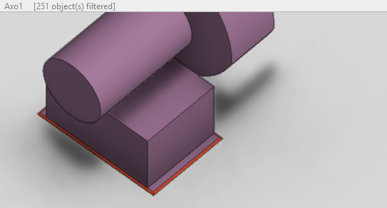
Weld penetration
You can generate a weld path along the seam where one object penetrates the planar face of another. If the target object is a plate and you need welds on both sides, you must insert the two welds separately.
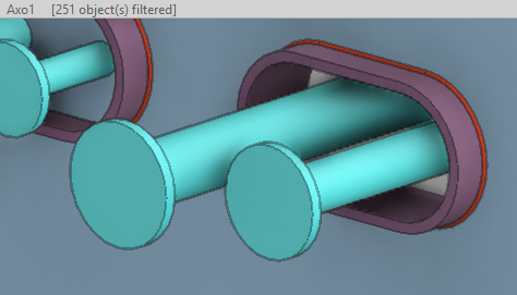
The program obtains the weld path by obtaining the boundary curve of the penetrating object or by cutting it with the target face. The boundary curve is preferred because it allows the weld path to include arcs. If the boundary curve of the penetrating object is not perpendicular to the target face, the arcs in the boundary curve are modeled as polylines. The weld path is trimmed by the boundary of the target face.
Prerequisites
-
The project administrator has defined Welds settings for the project.
Do the following:
- Select the Active logistics space, weld group, and weld system.
-
Select Weld tab > Insert group > Insert > Weld penetration.
-
Select the penetrating object, and press Enter. This should not be a Hull part.
-
Select the object being penetrated by picking near its planar face, and press Enter.