Flanged connections
In the 3D model, a flange can only be connected to another flange or wafer-style body if the connecting faces have been defined as compatible in the Compatibilities between connection faces configuration.
To include bolt sets and gaskets in the flanged connection, the required Bolt Sets and Gaskets must be assigned to a matching connection type pair and nominal size in the piping specification.
To visualize a bolt set, it must be assigned to the pressure rating of the connection face in the Bolt information configuration. Gaskets themselves are not visualized, but gasket gaps are shown if this is enabled in the Routing options.
Adding bolt sets and gaskets to piping specifications
In the Piping specifications section, you can assign bolt sets and gaskets to the flange joints of pipelines that use the given piping specification. Use the Component Classes named Bolt Sets for Flange Joints and Gaskets for Flange Joints to specify which bolt set and gasket, respectively, to use when two specific (same or different kinds of) connection faces connect to each other and the flanged connection has a specific nominal size.
For some connection types, a change in nominal size may require a different kind of bolt set. Therefore, you do not have to use the same bolt set or gasket for all nominal sizes of a given flange joint. If you select a different bolt set or gasket for some nominal sizes, an empty row separates the different types in the specification editor, as shown in the image below.

If the connected objects use different specifications, and the specifications define different materials for the given connection type, either Plant Modeller or the user selects which materials to use, as described below.
Assigning bolt sets and gaskets to flange joints
Normally, the piping specification defines which bolt set and gasket should be used for a given flange joint. If the objects participating in the flange joint do not use the same specification, Plant Modeller attempts to determine which specification to apply. In certain cases, Plant Modeller may prompt the user to select the correct specification or instruct them to designate one of the connected objects as the 'bolt owner'. When this occurs, the specification of the bolt owner object determines the joint materials.
How bolt sets are assigned to flange joints | How gaskets are assigned to flange joints | Setting the bolt owner by specification | Setting the bolt owner manually
How bolt sets are assigned to flange joints
When the connected objects are not using the same specification, Plant Modeller uses the following logic to decide which bolt set to use.
-
If one of the objects is the bolt owner:
-
Check the specification of the bolt owner object. If a bolt set is found, then use that bolt set.
-
Check the specifications of the pipeline of the bolt owner object, in the order the specifications are defined for the pipeline. If a bolt set is found, then use that bolt set.
-
-
If there is no bolt owner:
-
Check the specifications of the connected objects. If a bolt set is found in either specification, then use that bolt set. For example, if object #1 has no bolt set in its specification but object #2 does have one, then use the bolt set of object #2.
-
Check the specifications of the pipelines of the connected objects, in the order the specifications are defined for the pipelines, and select the first bolt set that is found. For example, if a bolt set is found in the second specification of object #1 and in the third specification of object #2, then use the bolt set of object #1.
-
How gaskets are assigned to flange joints
When the connected objects are not using the same specification, Plant Modeller uses the following logic to decide which gasket to use.
-
If the connection already has a bolt set, take the gasket from the same specification as the bolt set.
-
If the connection does not have a bolt set but one of the connected objects is the bolt owner:
-
Check the specification of the bolt owner object. If a gasket is found, then use that gasket.
-
Check the specifications of the pipeline of the bolt owner object, in the order the specifications are defined for the pipeline. If a gasket is found, then use that gasket.
-
-
If there is neither bolt set nor bolt owner:
-
Check the specifications of the connected objects. If a gasket is found in either specification, then use that gasket. For example, if object #1 has no gasket in its specification but object #2 does have one, then use the gasket of object #2.
-
Check the specifications of the pipelines of the connected objects, in the order the specifications are defined for the pipelines, and select the first gasket that is found. For example, if a gasket is found in the second specification of object #1 and in the third specification of object #2, then use the gasket of object #1.
-
Setting the bolt owner by specification
Routing a pipe or inserting or deleting a Standard Component in a location where one specification changes to another might prompt the user to select which specification to use for connecting the objects.

The Different Joint Material dialog opens when the operation that is being performed is connecting objects and these conditions are met:
-
The connected objects use different joint materials.
-
One of the connected objects specifies both the bolt set and the gasket, while the other object specifies only either the bolt set or the gasket.
-
The connected objects are checked out to the user.
The object whose specification the user selects in the dialog is designated as the bolt owner and determines which joint materials are used.
If the bolt owner cannot be set this way (for example, because the object is not checked out or the object is already connected to a bolt owner), the user is instructed to set the bolt owner manually.
Setting the bolt owner manually
In some cases of connecting objects that use different specifications, the user must be told to select the bolt owner object manually. This can happen, for example, if a connected object is not checked out or if the user is sliding a Standard Component and thereby causing existing connections to change. Setting the bolt owner can be done by selecting the required object with the Bolt owner: Set tool.
Checking object compatibility in flange joints
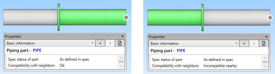
In the 3D model, you can use the Basic information tab of the Properties pane to check whether a given piping part is compatible with its current neighbors.
The "Compatibility with neighbors" (.Bd) attribute has the value "Ok" if the connection faces are compatible with each other and "Incompatible nearby" if they are not.
In the example below, the first pipe is properly connected to the flange at the weld point, but the second pipe has erroneously been routed directly to the gasket face of the flange, so the pipes are not connected to each other and Plant Modeller displays the second pipe as being incompatible with its neighbor.
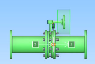
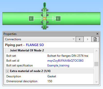
Checking connections in flange joints
In the 3D model, you can use the Connections tab in the Properties pane to see information on the connection nodes and the joint materials. Accessing this tab also visualizes the bolt sets in the 3D model, if Bolt information has been configured correctly.
If you are on the Connections tab and the Messages pane is open, you can see possible errors and warnings that the program might issue in regard to the flange joint. For example, if the flanged connection requires a bolt owner and it has not been set yet, the message pane displays a message such as "Warning: Specification 'DIN_H2A' and 'Example_training' are using different bolt sets".