Drawing styles
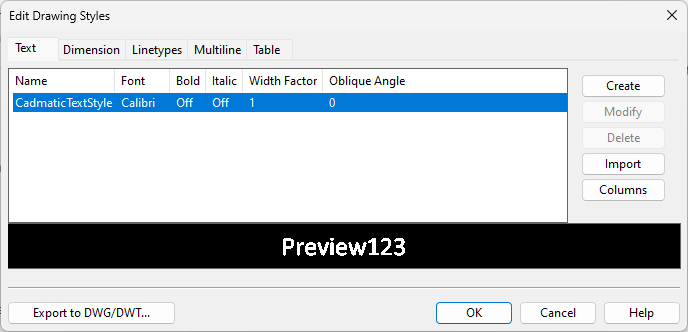
In the Project Environment dialog, [library] > Configuration > Common > Drawing styles allows the project administrator to define styles that designers can apply to 2D drafting objects in Plant Modeller and P&ID. Opening the configuration object displays the Edit Drawing Styles dialog which has separate tabs for managing text styles, dimension styles, linetypes, multiline styles, and table styles.
There are default styles that cannot be modified or removed. They must be present as fallback styles, in case a drafting object refers to a custom style that is not present in the current project environment.
Additional styles can be created manually or imported from DWG, DWT, and LIN files.
The entire drawing style configuration can be exported into a DWG or DWT file.
We recommend that you do not modify or delete drawing styles during a project, because it can be difficult to predict the impact on existing drawings and diagrams.
Text
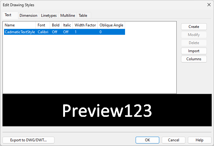
In the Edit Drawing Styles dialog, select the Text tab to manage text styles. A text style specifies a font and various style properties for that font.
You can create new text styles manually or import text styles from DWG or DWT files. Imported text styles may have properties that you cannot edit in CADMATIC.
Select a text style from the list to preview, modify, or delete the style. Starting to create or modify a text style opens the Modify Text Style dialog where you can define the style.
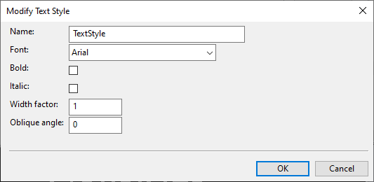
Text styles have the following properties:
-
Name – Enter a name for the style.
-
Font – Select the font to use. Make sure the font is available on all sites; CADMATIC does not distribute fonts to other workstations, and if the specified font is missing, a default font is used instead.
-
Bold – Select whether to display the text in bold type.
-
Italic – Select whether to italicize the text.
-
Width factor – Specify the width factor of the text. Value 1 means normal text, values smaller than 1 make the text narrower, and values larger than 1 make the text wider, while the height of the text always remains the same.
-
Oblique angle – Specify the slant angle of the text by entering a value between
You can assign a text style to a Dimension style or Table style, as well as to Text Properties that are used as annotation property defaults.
You should not delete text styles after designers have started using them. If a text style has been deleted, opening a document that has been using the style replaces the missing style with the default text style, and the user is not notified about this.
Dimension
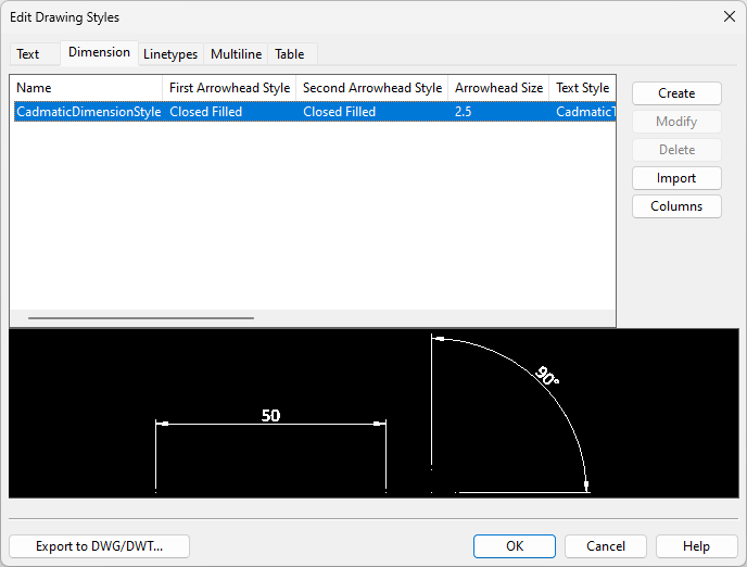
In the Edit Drawing Styles dialog, select the Dimension tab to manage dimension styles. A dimension style specifies what kind of lines, arrowheads, texts, and units are used when adding a dimension to a drawing.
You can create new dimension styles manually or import dimension styles from DWG and DWT files. Imported dimension styles may have properties that you cannot edit in CADMATIC. Imported non-default arrowhead styles are automatically mapped to the "None" arrowhead style.
Select a dimension style from the list to preview, modify, or delete the style. Starting to create or modify a dimension style opens the Dimension Properties dialog where you can define the style.
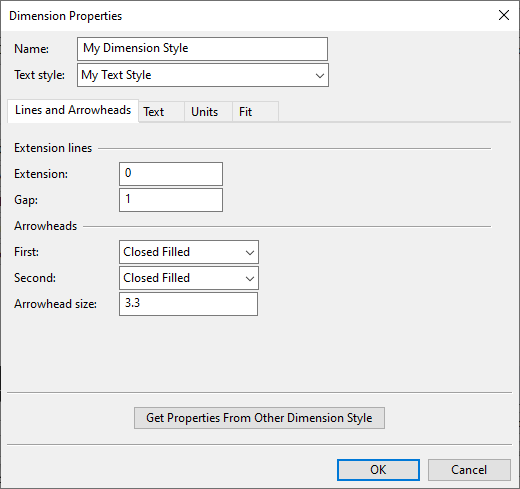
Dimension styles use a Text style for the text. The other properties are the same as those that are described in Dimension Properties.
Get Properties From Other Dimension Style allows you to copy all the properties from another dimension style.
You can assign a dimension style to Dimension Properties that are used as annotation property defaults.
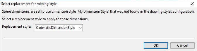
You should not delete dimension styles after designers have started using them. If a dimension style has been deleted, opening a document that has been using that style prompts the user to select which dimension style to use instead. Canceling the dialog replaces the missing style with the default dimension style.
Linetypes
In the Edit Drawing Styles dialog, select the Linetypes tab to manage linetypes.

You cannot create linetypes manually, you can only import them from DWG, DWT, and LIN files.
Linetype import supports shape files. The referenced shape must be found from the location that is specified in the linetype file, as shown below. The imported shapes are included to COS and replicated with the document to the other sites. When exporting a document that uses linetypes with shapes, the shapes are exported to the same folder as the drawing file, and the shape must be included when sending the document onward.
*CAD31,
A,.00025,-,0.2[CAD3,C:\temp\Dwg\CAD3.shx,s=1],-25
You can assign linetypes to Multiline styles and Table styles, as well as to Line Properties, Arc Properties and Circle Properties that are used as annotation property defaults.
If you have old P&I diagrams that use linetypes that are no longer supported, use Linetype mapping to map them to current linetypes.
You should not delete linetypes after designers have started using them. If a linetype has been deleted, opening a document that has been using the linetype replaces the missing linetype with the linetype of the associated layer, and the user is not notified about this.
Multiline
In the Edit Drawing Styles dialog, select the Multiline tab to manage multiline styles. A multiline is a line that can be drawn using multiple lines, fill colors, end caps, and so on.

In addition to 2D drafting, multiline styles can also be used in diagram object templates.
You can create new multiline styles manually or import multiline styles from DWG and DWT files.
Select a multiline style from the list to preview, modify, or delete the style. Starting to create or modify a multiline style opens the Modify Multiline Style dialog where you can define the style.
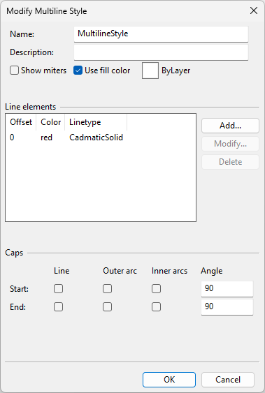
Multiline styles have the following properties:
-
Name – Enter a name for the style. The name cannot contain spaces.
-
Description (optional) – Enter a description for the style.
-
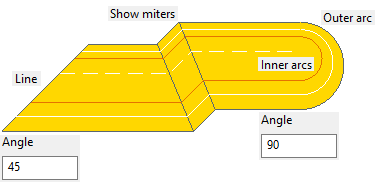
Show miters – Select this option to mark changes in line direction with a miter line.
-
Use fill color – Select this option to fill the spaces between the lines of the multiline with a color. Click the color picker to select the fill color or to set the fill color to be inherited from the layer where the multiline is drawn.
-
In the Line elements section, define the lines that create the multiline.
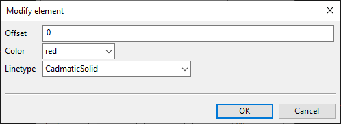
You can add, modify, and remove lines. Lines have three properties:
-
Offset – Offset from the reference line that the user draws when inserting a multiline into a drawing.
-
Color – Color of the line.
-
Linetype – Linetype of the line. See Linetypes.
-
-
In the Caps section, define how to draw the start and end of the multiline.
-
Line – Select this to draw a line where the multiline starts/ends.
-
Outer arc – Select this to draw an arc between the outer lines.
-
Inner arcs – Select this to draw an arc between each pair of inner lines.
-
Angle – Define the angle of the start/end of the multiline. The angle can be 10–170.
-
You can assign a multiline style to Multiline Properties that are used as annotation property defaults.
You should not delete multiline styles after designers have started using them. If a multiline style has been deleted, opening a document that has been using the style replaces the missing style with the default multiline style, and the user is not notified about this.
Table
In the Edit Drawing Styles dialog, select the Table tab to manage table styles. A table style defines the look of a table that has been copy–pasted from a third-party application or imported from a Microsoft Excel file to a Plant Modeller drawing (see Table) or P&ID diagram (see Table). Also DWG-based drawing sheets use table styles—see Edit Table.
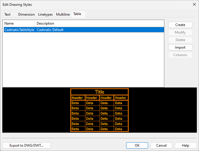
You can create new table styles manually or import table styles from DWG and DWT files. You should first import text styles from the DWG/DWT file, in case the table styles are using some custom text styles.
Select a table style from the list to preview, modify, or delete the style. Starting to create or modify a table style opens the Modify Table Style dialog where you can define the style.
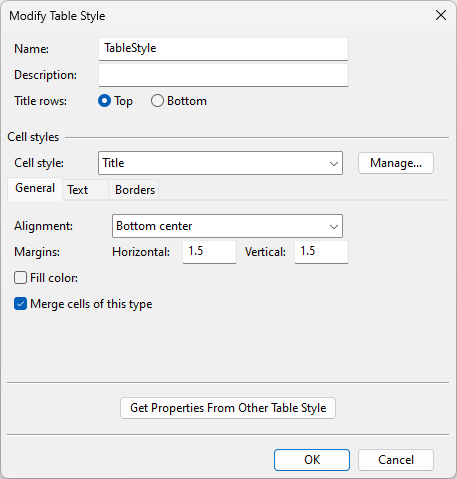
Table styles have these properties:
-
Name – Enter a name for the style.
-
Description (optional) – Enter a description for the style.
-
Title rows – Select whether the title row should be at the top or the bottom of the table.
-
Cell style – Select the cell style that you want to modify: Title cell style, Header cell style, or Data cell style.
Note: Although Manage allows you to create new cell styles, they cannot be applied to tables in this software version.
-
On the General tab, define the general properties of the cell style.
-
Alignment – Select how to align the contents of the cells.
-
Margins – Specify horizontal and vertical margins for the cells.
-
Fill color – Select this option and specify the fill color if you want to add a solid background color to the cells.
Note: Do not use fill colors in tables if documents might be exported using only black and white. Fill colors might cause both text and the background to appear black, making the text unreadable.
-
Merge cells of this type – This option has no effect in this software version. When importing tables, cells that are merged in the Excel file are also imported as merged cells.
-
-
On the Text tab, define the text properties of the cell style.
-
Text style – Select which text style to use. See Text.
-
Text height – Specify the text height.
-
Text color – Specify the text color.
-
Text angle – Specify the rotation angle of the text.
-
-
On the Borders tab, define the borders of the cell style.
-
Linetype – Select which linetype to use. See Linetypes.
-
Lineweight – Specify the lineweight of the borders. See Lineweights.
-
Color – Specify the color of the borders.
-
Double line, spacing – Select this option and specify the spacing value to draw double border lines.
-
Apply properties… – After defining the border settings, click the button that represents the borders that you want to draw with the given settings.
-
Get Properties From Other Table Style allows you to copy all the properties from another table style.
You should not delete table styles after designers have started using them. If a table style has been deleted, opening a document that has been using the style replaces the missing style with the default table style, and the user is not notified about this.