Concepts
Administrators of Support Designer should be familiar with the following concepts.
Standard and custom supports
Support Designer can be used to model standard supports and custom supports.
-
Standard supports are supports that can be manufactured based on a company-specific document that describes the support and its parameters. Typically, the standard document is a type drawing that shows the required parameters (which are usually the dimensions of the support) as symbols and describes their logical meaning in a dimensional picture of the support.
Accordingly, standard supports do not require separate drawings to be generated in CADMATIC—they only require that the Bill of Materials contains the name of the standard document and provides a value for each parameter that the given construction requires.
The following example identifies a standard secondary support that has one parameter, length:
Standard R101, Length=1100
Because standard supports will be manufactured according to what is described in the standard documents, designers should not modify the supports after the insertion into the 3D model, unless the standard support is used as a starting point for modeling a custom support.
-
Custom supports are completely customizable special constructions that require separate manufacturing drawings to be generated from the 3D model. One way to build a new custom support is to start the creation by selecting a standard support that resembles the intended construction and then modify the resulting model to achieve the intended construction. Also, there might be build scripts for building the regularly needed parts of a secondary support, such as different types of diagonals.
Designers can freely modify and even combine custom supports after the insertion into the 3D model, because manufacturing drawings must be generated anyway.
Primary and secondary supports
Support Designer can be used to build both primary supports and secondary supports.
-
Primary supports are, for example, U-bolts that are fastened onto the secondary support and hold the supported object in place.
-
Secondary supports are, for example, steel bars that are fastened onto a structural element such as a wall or a ceiling and carry the weight of the supported objects.
Logical objects
Support Designer uses some special logical objects that only exist in the context of this tool:
-
Location Plan
-
Support
-
Primary Support
-
Secondary Support
These logical objects are implemented using standard Plant Modeller objects: Groups, Attributes, Standard Components, and Beams.
-
Groups are used to set up the document and the object levels of the hierarchy.
-
Plant Modeller Attributes are used for storing object-specific data. Partly this data is only needed by the tool itself, and partly it is used by the user organizations for extracting material lists and printing labels to drawings.
-
Primary supports and secondary supports are the lower levels of the object hierarchy, and they are implemented using ordinary Standard Components and Beams, such as a pipe clamp and a 100 x 100 RHS profile.
Interfaces
Support Designer has some special interfaces that define how the program builds 3D objects for primary and secondary supports semi-automatically. For more information, see Interfaces.
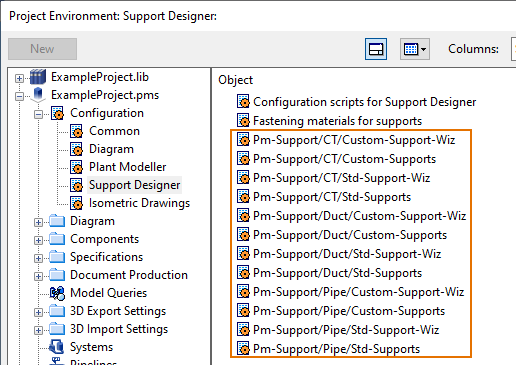
Configuration objects
In the Project Environment dialog of Plant Modeller, in [project] > Configuration > Support Designer, the project administrator defines the parameters that Support Designer uses to display a selection tool that allows the user to create a new primary or secondary support of a given type.
There are three main types of configuration objects:
- Configuration scripts for Support Designer is a configuration object which defines call-back scripts that Support Designer calls on different states (on create, on edit, and so on), for example, to assign a predefined set of attributes to the supports.
- Fastening materials for supports is a configuration object that defines the fastening materials to use in the supports. These materials, such as nuts, bolts, and washers are not modeled in 3D, but they are attached to the support geometry so that they can be included in the Bill of Materials.
- Templates for standard and custom supports and support wizards.
Support templates
The creation of a new support starts from the 3D designer selecting a support template that suits the given design context. Based on the selected template, Support Designer prompts the designer to define a set of parameters, which the designer usually does by selecting points and directions from the 3D model. Then, Support Designer builds the 3D objects and assigns them to the primary or secondary groups of the support.
The support templates are defined in the Parameters for secondary supports configuration objects of the project.
Each configuration object can contain a number of template records (supports that use the same interface), and each record stores the following:
-
A description that is unique among the records in the same configuration object.
-
The selected interface (see Interfaces), which defines the selection icon of the support and the build script to use. The drop-down menu with the selection icons acts as a class selector of records that use the same interface.
-
Project-specific parameter values for building the 3D objects with the build script.

Script API for Support Designer configuration scripts
CADMATIC uses a script API to configure certain Support Designer functionality. For example, when Support Designer needs a position ID for the support to be created, it calls a script function from the COS configuration object "Configuration scripts for Support Designer". This script function can implement custom position ID generation according to the needs of the user organization. There are currently 17 script function interfaces that Support Designer calls at runtime, and the user organizations can customize each of these.
For more information, see Configuration scripts for support designer.