Managing systems
You can manage the Systems of the project using either Plant Modeller or P&ID. The settings of each System are stored in COS attributes, as described in System related COS attributes.
Creating a new system in Plant Modeller or P&ID
Create the required Systems for the project.
Do the following:
-
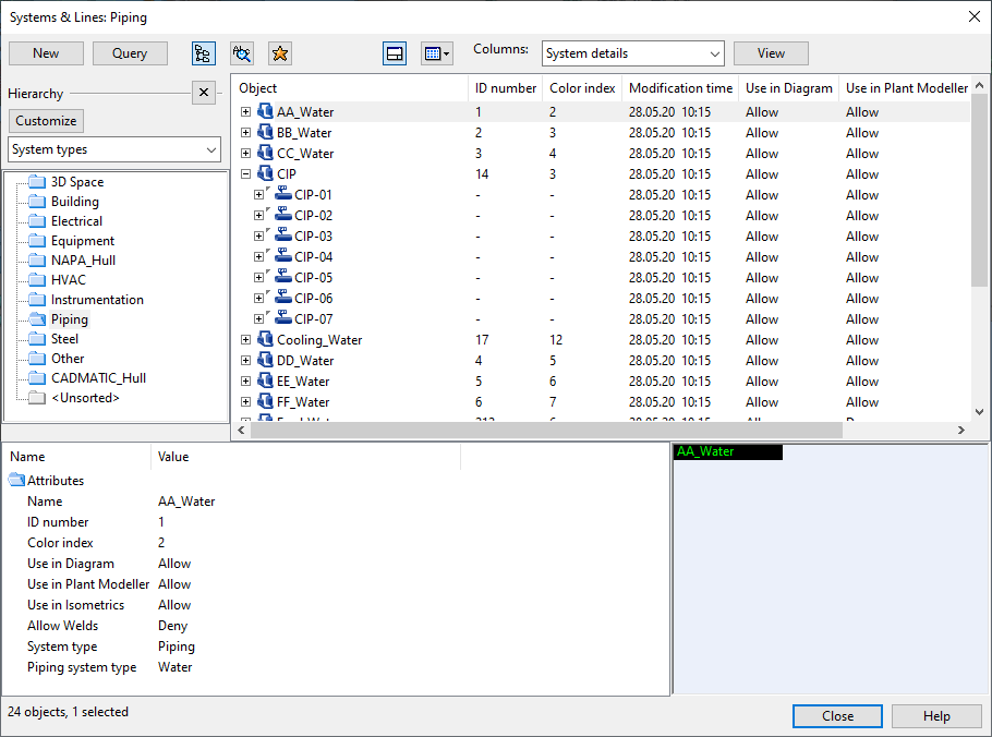
Select File > Environment > Systems and Lines. The Systems & Lines dialog opens.
-
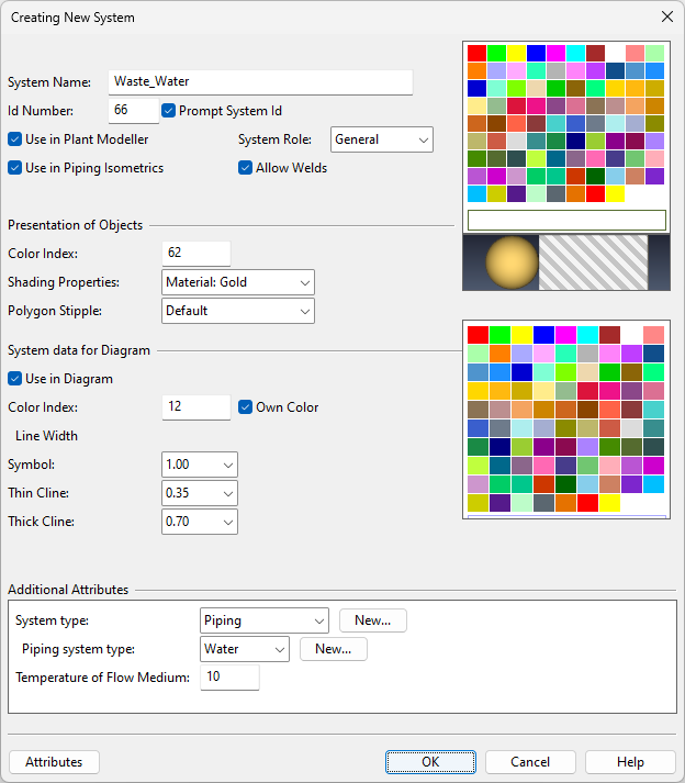
Select New > System. The Creating New System dialog opens.
-
Define the general properties.
-
System Name – Enter a name for the new System. The maximum length for the name is 100 characters.
Note: We do not recommend using special characters or spaces in the name.
-
Id Number – The System editor automatically assigns an ID number for a new System. If you want to choose the number yourself, select the Prompt System Id option and type the number in the field.
Note: We recommend using a suitable range of IDs for Systems that have a common purpose. For example, if all piping Systems are in the same range, it is easier to make System-based queries that select all piping objects. For more information on the numbering of Systems, see Id Number.
-
Use in Plant Modeller – If selected, the System is visible in Plant Modeller.
-
Use in Piping Isometrics – If selected, the System is visible in Piping Isometrics & Spools.
-
System Role – Select the role of this System.
- General – Most Systems use this role.
- Cableway – Only Systems that define cable trays should use this role. Selecting this role displays additional Definitions for Cable Router options.
- Cable – Only Systems that define cables should use this role. Selecting this role displays additional Definitions for Cable Router options.
For more information on the Cable Router related roles, see Cable tray systems and lines.
-
Allow Welds – If selected, the objects that use this System can be welded. This setting is displayed when System Role is "General" or "Cableway".
-
-
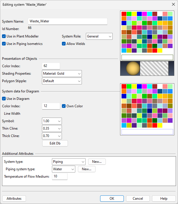
In the Presentation of Objects section, define the visual appearance of objects in this System.
- Color Index – This setting specifies the color of wireframe objects, and also that of shaded objects unless the Shading Properties setting specifies some other color to be used instead. You can select the color by clicking the color palette or by typing the index number of the required color. The colors are defined in the configuration object [library] > Configuration > Common > Colors , and the index number range is from 1 (red) to 84 (mint).
- Shading Properties – If set to "Lookup via color", the Color Index setting is used to find a matching shading color for shaded objects. If you want shaded views to use some other color, select a suitable shading style from the drop-down menu. The shading styles are defined in the configuration object [library] > Configuration > Plant Modeller > Surface Shading Setup.
- Polygon Stipple – This setting is not used anymore.
-
If P&ID is in use in this project, the System data for Diagram settings are displayed.
- Use in Diagram – If selected, the System is visible in P&ID.
- Color Index – By default, P&ID uses the same System color as Plant Modeller. If you want P&ID to use a different color for this System, select the Own Color option and then select the color from the color picker.
- Line Width – Define the line width of Symbols, thin connection lines and thick connection lines of objects that use this System.
-
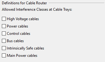
In the Definitions for Cable Router section, which is shown if you set System Role to "Cableway", the Allowed Interference Classes at Cable Trays options allow you to select which interference classes are available to cable trays that use this System.
-
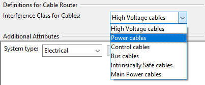
In the Definitions for Cable Router section, which is shown if you set System Role to "Cable", the Interference Class for Cables field allows you to select what is the interference class of cables that use this System.
-
In the Additional Attributes section, select which attributes to assign to this System and define their values. See Additional Attributes.
-
Click OK.
-
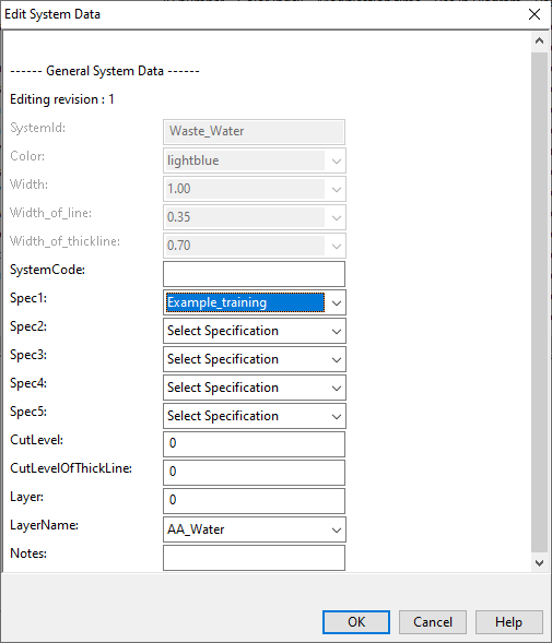
If P&ID is used, the Edit System Data dialog opens. Define the System specific settings for P&ID as appropriate, and click OK.
Creating a new system in Plant Modeller
Instead of using the Systems & Lines dialog, in Plant Modeller, you can also create new Systems via the Project Environment dialog.
First select File > Environment > All Library and Project, and then in the Project Environment dialog navigate to [project] > Systems.
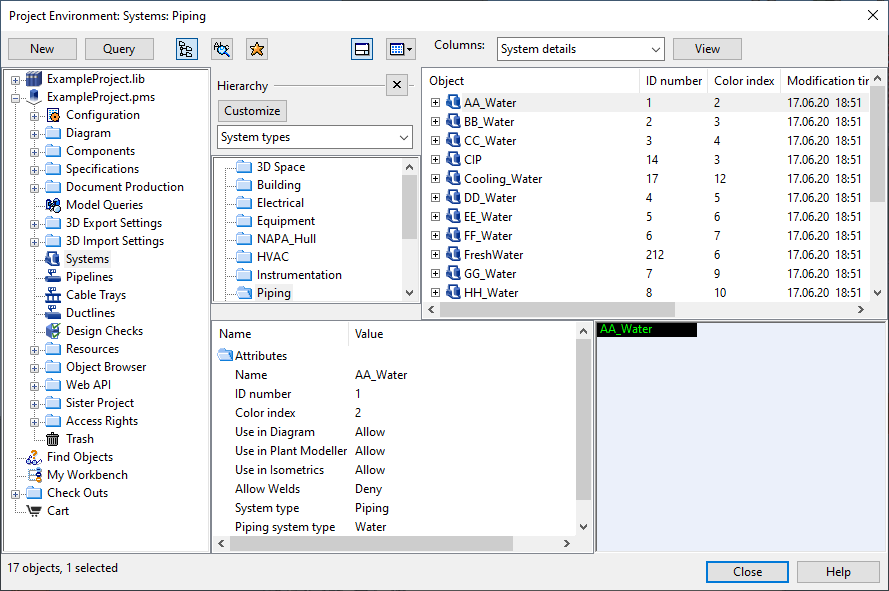
Note: If you open Project Environment from the CADMATIC desktop or from P&ID, you can only view existing Systems—you cannot create, edit or delete Systems.
Then, create the System in the same way as it is done when using the Systems & Lines dialog.
Creating a new system in P&ID
Instead of using the Systems & Lines dialog, in CADMATIC P&ID, you can also create new Systems via Insert > Systems > Define. This way, some of the System's properties will be automatically set—for example Use in Plant Modeller is disabled and Use in Diagram is enabled. First you are prompted to enter a name for the new System, and then you fill in the System data using the standard database card dialog of P&ID.
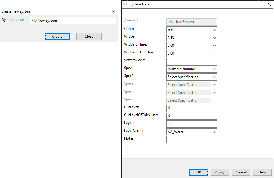
Note the following settings:
-
CutLevel – Specifies the cut level of lines drawn with a thin line. Value must be in the range [0,255]. See also Options.
-
CutLevelOfThickLine – Specifies the cut level of lines drawn with a thick line (for example, primary pipe in Example Project). Value must be in the range [0,255].
-
Layer / Layername – In the LayerName field, select the layer where objects that use this System should be when the diagram is exported. See also Drawing export configuration.
Editing a system
You can edit existing systems in Plant Modeller and P&ID.
Do the following:
-
Select File > Environment > Systems and Lines. The Systems & Lines dialog opens.
-
Double-click the System to be edited. The Editing system '<name>' dialog opens.
-
Edit the settings as appropriate. If P&ID is used, you can edit the database data by clicking Edit Db.
-
Click OK.
Deleting a system
You can delete Systems that do not have any lines (Pipelines, Ductlines, Cable Trays).
Do the following:
-
In Plant Modeller or P&ID, select File > Environment > Systems and Lines. The Systems & Lines dialog opens.
-
Right-click the System you want to remove and select Delete from the context menu. You are prompted to confirm the action.