Options

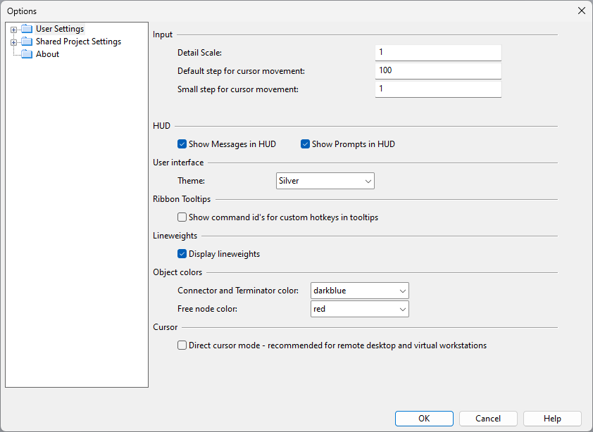
In CADMATIC P&ID, selecting File > Settings opens the Options dialog where each user can adjust the user interface according to their preferences and the project administrator can define shared project settings that affect all users.
User Settings
In the Options dialog of P&ID, the User Settings section allows you to specify settings that only affect your own use of the application.

User Interface
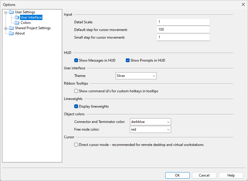
In the User Interface view, you can change settings that affect the general user interface.
Input
- Detail Scale – Specifies the zoom level to jump to when using the Zoom Detail command, from 0.1 to 9999.
HUD
"HUD" stands for head-up display, and refers to displaying useful information where the user's focus point typically is (near the cursor).
-
Show messages in HUD – If selected, error notifications and other information are shown next to the cursor. If not selected, the information is only shown in the message pane (if displayed).
-
Show prompt in HUD – If selected, information about what the program expects the user to do next is shown next to the cursor and in the status bar. If not selected, the information is only shown in the status bar.
User interface
- Theme – You can set the user interface to use one of the following themes: Silver, Black, or Blue.
Ribbon Tooltips
- Show command id's for custom hotkeys in tooltips – When selected (default), the IDs (string or numeric) of command hotkeys are shown in the ribbon. See Customizing the ribbon.
Lineweights
- Display lineweights
Cursor
-
Direct cursor mode
Note: Direct cursor mode allows the arrow keys to be used for moving even if the cursor position is locked with 5 or 6.
Colors

Color Palette
The color palette determines the colors that CADMATIC P&ID uses both internally as well as in exported files. You can select which color palette to use:
-
Use Shared Colors (default) – Select this option to use the common color palette that your administrator can define for your organization in [library] > Configuration > Common > Colors or by clicking Edit Shared Colors in this view.
-
Use Personal Colors – Select this option to use the personal color palette that you can define by clicking Edit Personal Colors.
Reset Personal Colors resets your current personal color palette by replacing it with the common color palette that administrator has defined.
Drawing Background and Highlight Colors
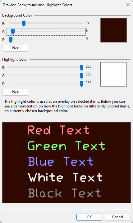
You can change the background color of the diagram window and the color that is used to highlight selected objects, without affecting diagram exports.
Edit – Opens the Drawing Background and Highlight Colors dialog.
-
Background Color – You can adjust the RGB values of the background color by dragging the color sliders or by clicking Pick and selecting the color from the color palette.
-
Highlight Color – You can adjust the RGB values of the highlight color by dragging the color sliders or by clicking Pick and selecting the color from the color palette.
Reset to Defaults – Restores the default background and highlight colors.
Shared Project Settings
In the Options dialog of P&ID, the Shared Project Settings section allows the project administrator to define settings that affect all project users.
Also users can change these settings, but the changes are only applied to their own environment and restarting the application restores the administrator-defined settings.

Font | Drawing Export | System Default | Symbol Default | Name Generation Rules | Automatic Update | Propose Save and Check-in | Compare with 3D | Model Coordinates | Document Revision and Publishing | Connections | Miscellaneous | Consistency Check
Font
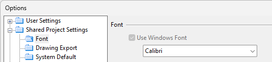
Select the Microsoft Windows font to use. If an old diagram uses a font that is no longer available, the Arial font is used instead.
Drawing Export

-
Format – Select the file format to use, and click Advanced to define format-specific options.
The Advanced button opens a dialog for defining format-specific settings, if available for the selected format. For example, for BMP/JPEG/PNG export you can specify drawing size, page layout as portrait or landscape, and whether to use the 2D export setting colors or just black and white.
-
Output Directory – Select the output directory.
-
Template Drawing – Select the template drawing to use in drawing export.
-
View Exported File – Select this option to automatically open the exported file after the export.
-
Explode Proxy Objects – Select this option to convert connection lines into polylines in DWG and DXF export. This can make it easier to modify the connection lines in third-party software.

System Default
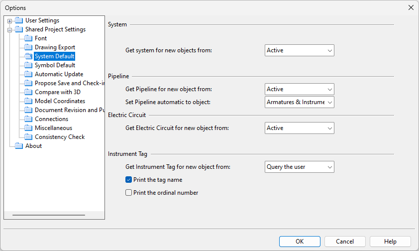
Pipeline
-
Set Pipeline automatic to object – Select whether pipeline should be automatically set only to armatures or to both armatures and instruments.
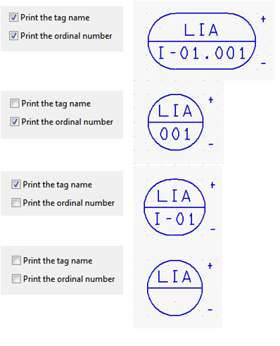
Instrument Tag
-
Print the tag name, Print the ordinal number – Select whether to print tag name and ordinal number to instrument tags.
Symbol Default
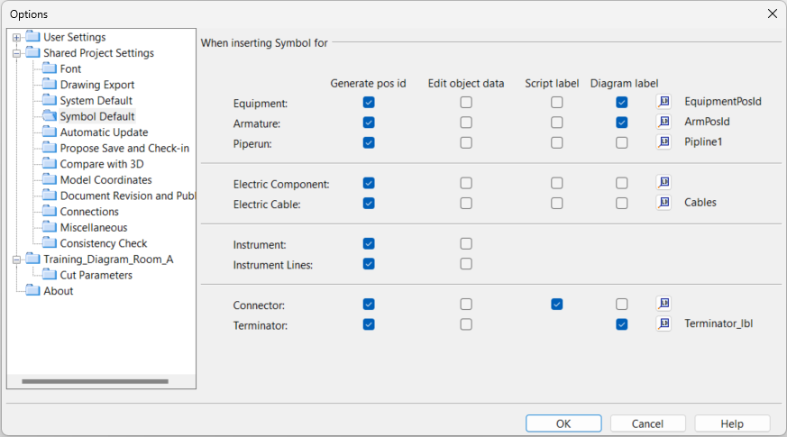
You can specify which automatic functions are performed when inserting objects:
-
Generate position IDs automatically. (This is rarely used for pipe runs.)
Note: This requires setting up the file set_defaults.mac correctly for the given object type. See the 'set_defaults' script.
-
Edit object data immediately after the insertion.
-
Insert script label immediately after the insertion.
-
Insert diagram label immediately after the insertion.
The settings can be defined for the following object types:
- Equipment
- Armature
- Pipe run
- Electric component
- Electric cable
- Instrument
- Instrument line
- Connector
- Terminator
After selecting to insert labels for a given object type, click the label button  to select the label from the library.
Name Generation Rules
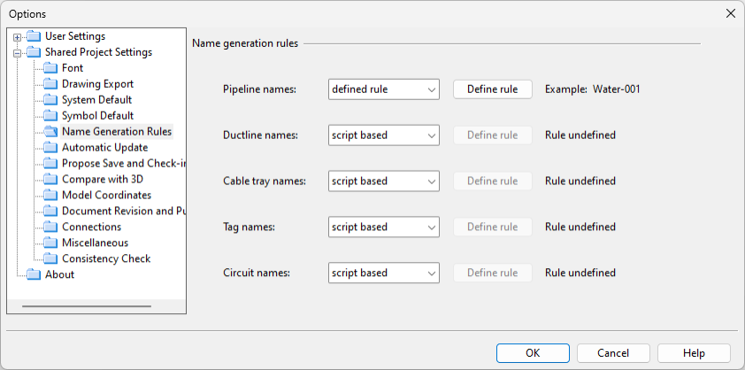
You can specify whether new line names should be generated via the 'set_defaults' script or line type specific rules.
If you select the 'defined rule' option, clicking Define rule opens the Edit Name Generation Rules editor of the given line type.
Note: P&ID and Plant Modeller use the same line name generation rules. Changing the rules for pipelines, ductlines, or cable trays in one application will affect the generating of line names in both of them.
Automatic Update
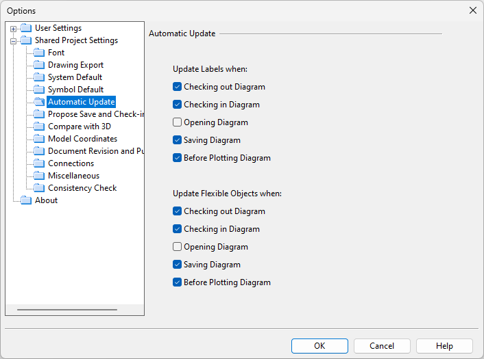
You can define how labels and flexible objects are updated. Flexible objects are, for example, valve templates that can change their look according to the library object.
Automatic update can be set to occur when checking out a diagram, checking in a diagram, opening a diagram, saving a diagram, or before plotting a diagram.
Designers can also manually update labels (Update) and flexible objects (Update) in the active diagram.
Propose Save and Check-in
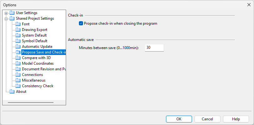
Check-in
-
Propose check-in when closing the program – If selected, the users are prompted to check in all checked-out diagrams when closing the application.
Automatic save
-
Minutes between save (0...1000min) – Define how often the program should prompt the users to save their unsaved diagrams. When the save dialog opens, the user can select which diagrams to save or skip the saving. If there is no need to prompt the users, set the value to 0.
Compare with 3D
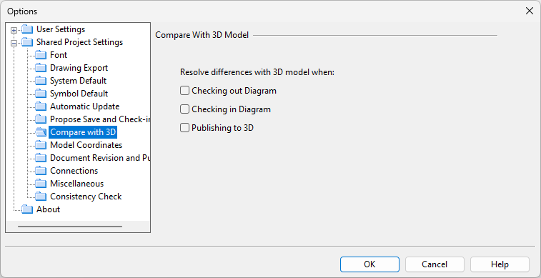
You can select whether the program should automatically run the Compare with 3D model function when a diagram is checked out, checked in, or published to the 3D model. If the diagram objects are published to 3D and there are differences between the diagram data and the 3D model data, a comparison dialog opens for reviewing the differences.
Model Coordinates
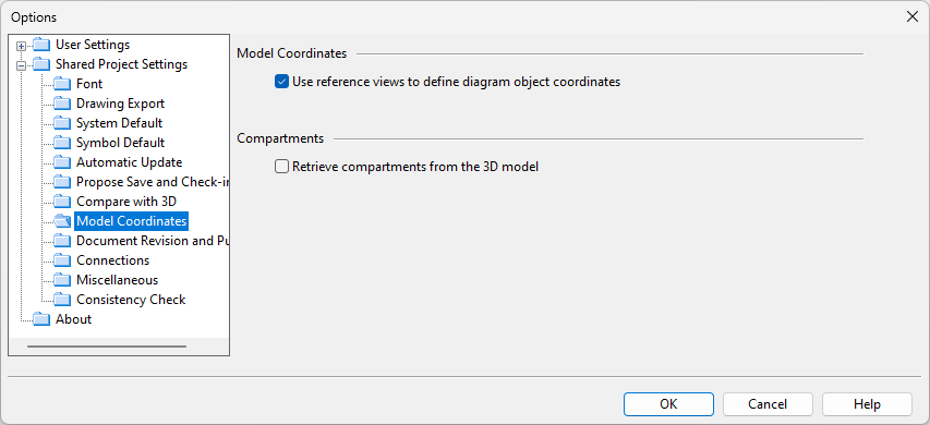
Model Coordinates
-
Use reference views to define diagram object coordinates – If selected, reference views are used to define coordinates for diagram objects. This setting can be used with integration to Plant Modeller: when an object that is defined in a diagram is inserted into the 3D model, the cursor is automatically positioned in the correct location.
Compartments
-
Retrieve compartments from the 3D model – If selected, diagram objects retrieve compartment information from the 3D model.
For more details, see Publish location and compartments from P&ID to Plant Modeller.
Document Revision and Publishing
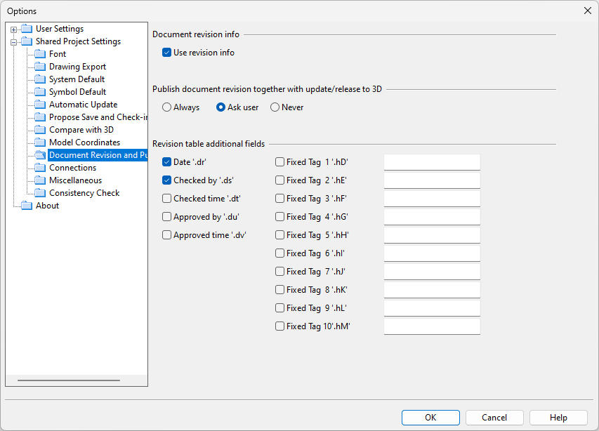
Document revision info
-
Use revision info – Select this option to use document revisions. When enabled, publishing a document prompts the user to select whether to create a new document revision.
Publish document revision together with update/release to 3D
-
If use of revision information is enabled, select whether updating diagram data to the 3D model also publishes the document revision information: Always, Ask user (default), or Never.
Revision table additional fields
-
Select which additional tags to include in revision information. For the fixed tags you can define a descriptive name to be displayed to the users, so that they know what to enter in the value field.
Connections
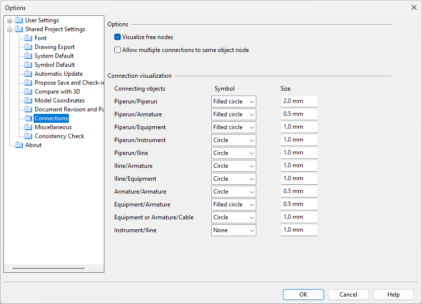
Options
- Visualize free nodes – If selected, free (unconnected) nodes are visualized in diagrams. If not selected, designers can show or hide free nodes as described in Free nodes.
- Allow multiple connections to same object node – If selected, a single object node can accept multiple connections. If not selected, a single node only accepts one connection at a time.
- Get NS value from connection node when beginning pipeline from it – If selected, starting a new pipe from the connection node of an armature, equipment, or an existing pipe will derive the new pipe's nominal size from that node.
Connection visualization
-
Select how to visualize different types of connections, such as the connection between two pipe runs or the connection between an instrument and an instrument line. For each connection, you can select the symbol to use (none, circle, or filled circle) and the size of the symbol.
Miscellaneous
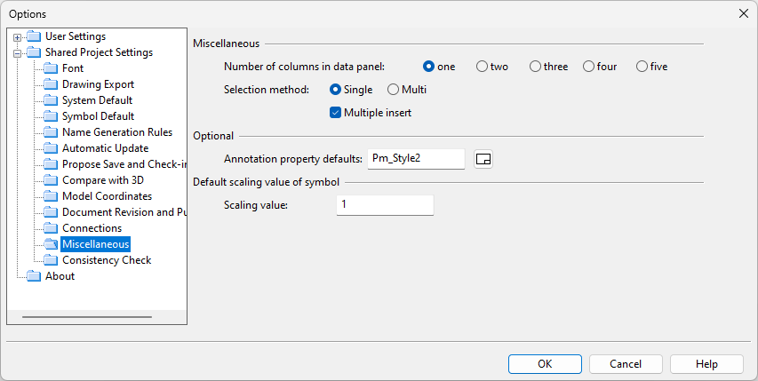
Miscellaneous
-
Number of columns in data panel – Select how many columns (1–5) of data to have in database cards.
-
Selection method
-
Single – Selecting an object by clicking deselects the previously selected object. (Multiple objects can be selected by holding down Shift or using other kinds of selection methods.)
-
Multi – Multiple objects can be selected by clicking them one by one.
-
-
Multiple insert – If selected, the same diagram template object can be inserted multiple times, until the user cancels the insertion.
Optional
-
Annotation property defaults – Select the Annotation Property Defaults that the tools on the Drafting tab should use by default in new diagram documents. The user can override this selection when creating a New diagram, or via the Properties tools of the active diagram.
Default scaling value of symbol
-
Scaling value – Select what to use as the default scaling value of new symbols inserted to diagrams, from 0.1 to 100.
Object colors
- Connector and Terminator color – Select the color to use for connectors and terminators.
- Free node color – Select the color to use for free nodes.
Consistency Check
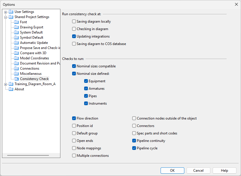
Run consistency check at
Select when to run consistency checks automatically.
-
Saving diagram locally – If selected, consistency checks are run when the user is saving a diagram locally.
-
Checking in diagram – If selected, consistency checks are run when the user is checking in a diagram.
-
Updating integrations – If selected, consistency checks are run when the user is saving a diagram in COS and selects to update the diagram data in integrated applications (Plant Modeller, Electrical).
-
Saving diagram to COS database – If selected, consistency checks are run when the user is saving a diagram in COS.
Tip: You can also run consistency checks manually, as described in Consistency check.
Checks to run
Select which checks to include whenever a consistency check is run.
-
Nominal sizes compatible – This check reports if nominal sizes are incompatible between connected diagram objects (such as a piperun and valve), mapped nodes, or branches where the main run is not split (the branch must not be larger than the main run).
-
Nominal size defined – This check reports if a diagram object (or the line to which it belongs) does not have a nominal size defined.
You can specify which object types are to be checked.
-
Flow direction – This check reports if all the flow directions at a connection node are either "in" or "out".
-
Position id – This check reports if a diagram object does not have a position ID defined.
Checked object types: Armature, Cable, Equipment, Instrument.
-
Default group – This check reports if a diagram object is assigned to the Default System or Default Line.
Checked object types: Armature, Equipment, Instrument, all line types.
-
Open ends – This check reports if either end of a line (of any type) is unconnected.
-
Node mappings – This check reports if a diagram object's node is not mapped to one of the nodes of the linked component model.
Checked object types: Armature, Equipment.
-
Multiple connections – This check reports if multiple lines (of any type) are connected to the same node.
Checked object types: Armature, Equipment, Instrument.
-
Connection nodes outside of the object – This check reports if a connection node is outside the bounding box of its host object.
-
Connectors – This check reports if a connector is either unconnected or not using the same pipeline or nominal size at both ends.
-
Spec parts and short codes – This check reports if a Part Code (DmPartCode) is not in the specification or does not have the given Short Code or nominal size.
-
Pipeline continuity – This check reports if a pipeline is discontinuous.
-
Pipeline cycle – This check reports if a pipeline loops back into itself, forming a flow cycle.
About
In the Options dialog of CADMATIC P&ID, the About view displays the product name, the release version, and the date when the version was built.
You can click Legal Notices to see a list of third-party software used by CADMATIC P&ID. The list opens in the default text editor program of your computer.
