Model
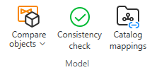
On the Data tab, the Model group includes the following tools.
Compare objects
P&ID – 3D integration allows Plant Modeller to link objects that have the same position ID in P&ID and in the 3D model. Automatic linking occurs if diagram objects are first published from P&ID to 3D and then inserted into the 3D model in Plant Modeller. If the position ID is first used in the 3D model and only then published from the diagram, the Plant Modeller user must link the objects manually.
When diagram objects are linked to the 3D model, you can check for differences in data. If the data is correct in P&ID (typically, because the diagram has been edited after the objects were inserted into the 3D model), the P&ID user can resolve the differences by applying 3D model data to the diagram. If the data is correct in P&ID and the diagram has been published to 3D, the differences must be resolved in Plant Modeller.
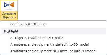
Compare with 3D model | Highlight
Compare with 3D model
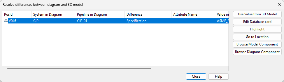
Select Data tab > Model group > Compare Objects > Compare with 3D model opens a dialog that shows items that have an integration link to the 3D model and there are differences in the data between the 3D model and P&ID.
Differences that are shown are:
- Different values in integration attributes modifiable in both P&ID and 3D model.
- Different component model
- Different system for equipment
- Different system and pipeline for valve
- Different nominal sizes for valve (first two key dimensions)
- Different system, material, name, interference class, or maximum length for cable
Each difference is shown on a separate row. You can sort the list by clicking the column headers.
If the value is correct in P&ID, the difference must stay in the list until the respective command is used in 3D and the Plant Modeller user resolves the difference.
You can multi-select list items before selecting a command.
- Use Value from 3D Model – Replaces the value in the diagram with the value from the 3D model. Multiple differences can be resolved by multi-selecting.
- Edit Database card – Opens the database editor for defining an alternative value.
- Highlight – Highlights the object in the active diagram.
- Go to Location – Moves the cursor to the selected object in the diagram.
- Browse Model Component – Shows the component model used by the 3D model.
- Browse Diagram Component – Shows the component model used by the diagram object.
Note: In File > Settings > Compare with 3D, the project administrator can set Compare with 3D to be automatically run when checking a diagram out or in in P&ID or before publishing to 3D.
Highlight
Select Data tab > Model group > Compare objects > Highlight to highlight diagram objects that are already modeled in 3D. Using these commands requires that integration is enabled and the objects have a link between 3D and P&ID.
-
All objects installed into 3D model
-
Armatures and equipment installed into 3D model
-
Armatures and equipment NOT installed into 3D model
Consistency check

Consistency checks can be executed either manually or automatically as part of certain operations. In File > Settings > Shared Project Settings > Consistency Check, the project administrator can specify the required consistency checks and the operations that will trigger these checks automatically.
You can initiate these checks in the active diagram by selecting Data tab > Model group > Consistency Check. If any issues are detected, the Consistency Check dialog opens, displaying the results.

You can select a check result from the list to investigate and possibly correct the issue.
- Edit Object – Opens a dialog for editing the data of the selected object. You might be prompted to select whether to generate a position ID for the object.
- Edit System – Opens a dialog for editing the system of the selected Equipment type object.
- Edit Line / Edit Pipeline / Edit Tag / Edit Circuit – Opens a dialog for the editing the line, pipeline, tag, or circuit data of the selected object.
- Assign to System – Opens the object browser for selecting the system to which to assign the selected Equipment type object.
- Assign to Line / Assign to Pipeline / Assign to Tag / Assign to Circuit – Opens the object browser for selecting the line, pipeline, tag, or circuit to which to assign the selected object.
- Reverse Flow Direction – Reverses the flow direction of the selected Piperun type object.
- Zoom Extents Selected – Zooms to the extents of the selected object.
- Go to Location – Hides the Consistency Check dialog and moves the cursor to the location of the selected object. Press Esc to return to the dialog.
Some commands such as reversing of flow direction are also available from the context menu.

If you manage to correct a reported issue, the given check result is automatically removed from the list.
Catalog mappings

Select Data tab > Model group > Catalog mappings to define rules that allow diagram objects with specific data values to be automatically mapped to Catalog Parts used by Plant Modeller.
For details, see Catalog mapping.