Active
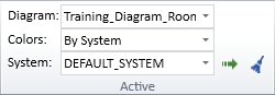
On the Home tab, the Active group contains the following tools.
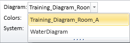
Diagram
In the Active group, the Diagram field shows "No Active Diagram" if no diagrams are open, otherwise it shows the name of the currently active diagram. If you have several diagrams open, you can change the active diagram from the drop-down menu.
You can also change the active diagram from the Arrange Windows menu in the P&ID status bar. There you can also see whether each diagram has been opened in 'edit' or 'browse' mode.
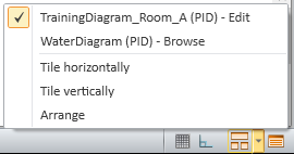
For more details on the status bar, see User interface.
Colors
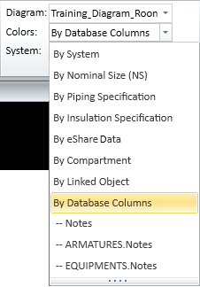
In the Active group, the Colors field displays what is the current coloring mode of the active diagram. Opening a diagram sets the coloring mode to the default, which is 'By System', and you can select a different coloring mode from the drop-down list.
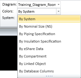
These coloring modes are available:
-
By System – Objects are colored according to their System. System colors are defined in File > Environment > Systems and Lines.
-
By Nominal Size (NS) – Objects are colored according to their Nominal Size value.
 Show/hide example
In this example, the colors make it easy to see that pipeline WAA0051 (NS=100) and valve V005 (NS=80) have different Nominal Size values.

-
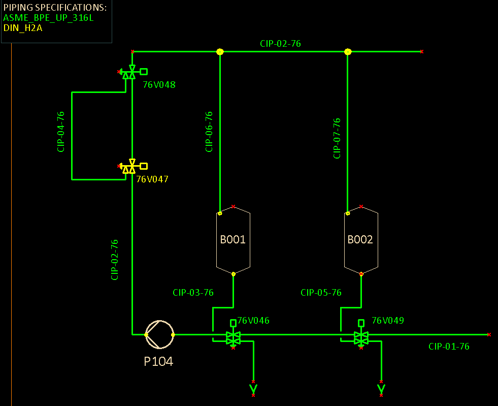
By Piping Specification – Objects are colored according to color definitions in piping specifications. If valves and pipe run parts use another specification than the first specification option from the pipeline, project administrator must add the required specification columns to the ARMATURES table—see ARMATURES.
Show/hide example
In this example, the colors show that all pipelines and valves use piping specification ASME_BPE_UP_316L except valve V047 which uses DIN_H2A.
-
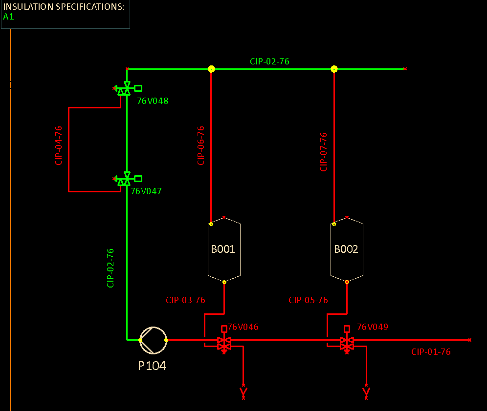
By Insulation Specification – Objects are colored according to color definitions in insulation specifications.
Show/hide example
In this example, the colors show that pipeline CIP-02 uses insulation specification A1 (green) and that the other pipelines do not use any insulation specification (red).
-
By eShare Data – Objects are colored according to an object categorization obtained from CADMATIC eShare. You can use this function when your Windows account is defined in the eShare user list and eShare project administrator has given your account permission to access the specified data.
Show/hide details
Selecting the By eShare Data option opens the Select Category dialog where you can select which eShare category to use for the coloring.
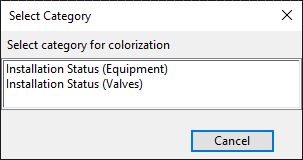
Note: From this list you should select an attribute category, Smart Point Type, or Status Tracking item defined in eShare that targets the following attributes: Equipment Position Id (.n5), Instrument Position Id (ipo) and Valve Position Id (vpo). All other selections are not applicable.
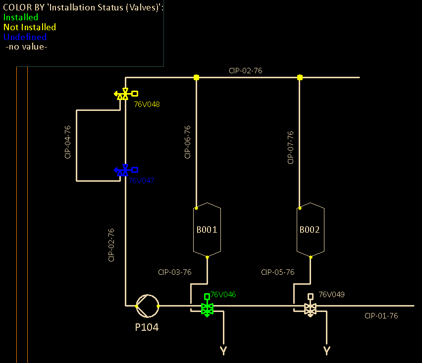
Selecting a category from the list colors the active diagram based on the general active colors functionality and the color palette of the project. P&ID does not get color definitions from eShare.
Show/hide example
In this example, the diagram makes it easy to see what is the installation status of each valve. Typically, the installation status is set on-site, using the CADMATIC eGo tablet application, and then uploaded from eGo to eShare.
-
By Compartment – Objects are colored according to compartment (if defined in the object data).
-
By Linked Object – When the same P&ID data object has multiple instances in the active diagram or in different diagrams, those object instances are linked, and this option allows you to easily see which objects in the active diagram are linked objects. The colors also indicate whether the linked object is owned by the active diagram or some other diagram. For more information on the linking, see Manage linked objects.
-
By Database Columns – Objects are colored according to values of one or more database columns.
Show/hide details
Selecting the By Database Columns option opens the Select Column(s) for Color Information dialog where you can define which database columns to use for the coloring.
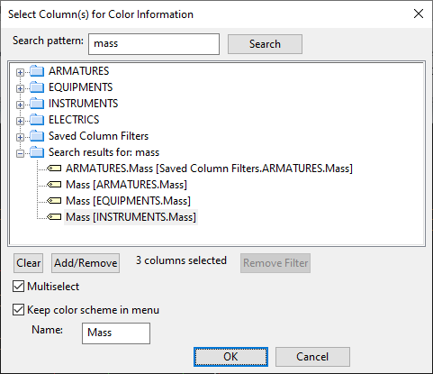
In this dialog, you can do the following:
-
Select a column from the appropriate main table: ARMATURES, EQUIPMENTS, INSTRUMENTS, or ELECTRICS.
-
Select Multiselect and add several columns from the main tables, one at a time, by selecting the column and clicking Add/Remove. (You can start again, if needed, by removing all selections with Clear.)
-
Quickly find specific columns: enter a search string in Search pattern and click Search.
-
Re-select columns from Saved Column Filters. This dynamic group shows the last five selections, and they are also listed in the Colors drop-down menu.
-
Add a column selection permanently to the Colors drop-down menu: select the columns, select the Keep color scheme in menu option, and type the name to show in the menu.
Show/hide example
The 'Notes' database column can be used to convey information about changes that need to be made. By using a color scheme based on the values of this column, the diagram designer can easily see which objects have notes. In the image below, 'Notes' is a user-defined (permanent) multi-column selection, and 'ARMATURES.Notes' and 'EQUIPMENTS.Notes' are recent (temporary) single-column selections from specific main tables.
-