User interface
The CADMATIC P&ID application window includes the following main elements.
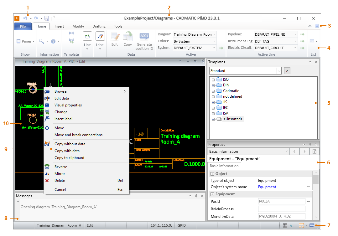
- Customizable Quick access toolbar.
- Title row, displaying <diagram name>/<workspace name> – <application version>.
- Button for accessing the Online help.
- Ribbon toolbar, consisting of tabs with command buttons (some including a drop-down menu) arranged into tool groups.
- The default location for the Properties pane, Object templates pane, and Markups pane.
- Status bar, displaying information fields on the left and in the middle and command buttons on the right.
- The default location for the Messages pane.
- Context menus, opened by right-clicking the active diagram.
- Working area, shows the open diagrams.
User interface elements are described below.
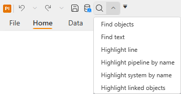
Quick access toolbar
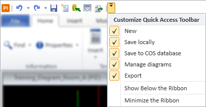
You can add your most frequently used commands to the Quick Access Toolbar, and remove them if usage decreases. If a command you add to the quick access toolbar includes a menu in the ribbon toolbar, then the menu is available also in the Quick Access Toolbar.
-
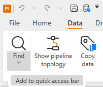
You can add items to the Quick Access Toolbar by right-clicking the command in the File menu or the ribbon toolbar and selecting Add to quick access bar.
-
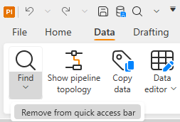
You can remove an item from the Quick Access Toolbar by right-clicking the item, either in its original location or in the Quick Access Toolbar, and selecting Remove from quick access bar.
You cannot remove the default commands: Undo and Redo.
-
You can position the Quick Access Toolbar above or below the ribbon toolbar, and minimize or restore the ribbon toolbar, through the customization menu.
Tabs
The ribbon toolbar consists of the File menu and tabs that contain toolbar buttons arranged into groups.
Working area
The working area is where the actual diagrams are created and viewed.
When you have several diagrams open, use the menu of the Windows status bar button  to switch between the diagrams or to arrange the diagram windows.
Right-clicking the active diagram opens a menu with commands that are applicable in the given context. All context-menu commands are described in Context menus, and object type specific context menus are shown in P&ID object types.
Properties
The Properties pane shows the database data of the selected object and allows editing the data.
For more details, see Property Pane.
Object templates
The Object templates pane includes the available object templates that define diagram symbols and connection lines.
For more details, see Template Pane.
Markups
The Markups pane shows markups added to diagrams in CADMATIC eShare.
For more details, see Markups Pane.
Messages
The Messages pane can display various messages such as the commands the user selects, the information the program shows to the user, and error messages.
For more details, see Message Pane.
Status bar
The bottom of the application window displays the status bar.
On the left, the status bar displays fields that can show the following information:

-
The prompt shown to the user while performing a command, such as 'Pick objects to set', and 'Ready' after the command has finished.
-
The active diagram's name, if several diagrams are open.
-
The active diagram's editing status, such as 'Browse', 'Edit', or 'Modified'.
-
The active diagram's origin point.
-
The selected object's origin point, or the cursor location if Track location in status bar is enabled.
-
The cursor's restricted status, such as 'X-fixed', 'Y-fixed', or 'Locked to line'.
-
'GRID' is shown when the grid is displayed (F7).
-
'ORTHO' is shown when cursor movements prefer orthogonal directions (F8).
-
'SNAP' is shown when snapping to grid points is enabled (F9).
-
'Automatic Insert' is shown when the active insertion command will automatically restart until the user cancels it (Esc).
On the right, the status bar displays action buttons:

-
 – Turns both grid and snapping on or off. When enabled, the grid is displayed and the cursor snaps to the grid.
 -
 – Turns Ortho on or off. When enabled, the program tries to keep connection lines orthogonal (aligned with grid points).
 -
– Opens a menu with the following items:
-
A list of open diagrams. Select a diagram from the list to make that diagram the active diagram.
-
Tile Horizontally – Select this to arrange the open diagrams horizontally.
-
Tile Vertically — Select this to arrange the open diagrams vertically.
-
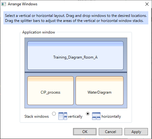
Arrange – Select this to open a dialog where you can arrange the layout of the open diagram windows by dragging.
-
-

 – Shows the Message Pane if it is hidden.
Context menus
Context menu for selecting objects | Context menu for one object | Context menu for multiple objects | Context menu for selecting objects in commands
Context menu for selecting objects
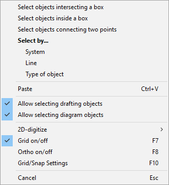
When nothing is selected and there is no active command, right-clicking the diagram opens a context menu with the following commands.
|
Command |
Shortcut |
Description |
|---|---|---|
|
|
Allows selecting objects that are partly or completely inside a rectangle defined by selecting two corner points. The options Allow selecting drafting objects and Allow selecting diagram objects define what this command can select. |
|
|
|
Allows selecting objects that are completely inside a rectangle defined by selecting two corner points. The options Allow selecting drafting objects and Allow selecting diagram objects define what this command can select. |
|
|
|
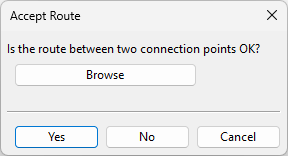
Allows selecting diagram objects, connection lines, and connected labels along a route defined by selecting two connection points. There can be several possible routes between the selected points. In the Accept Route dialog, selecting Yes accepts the currently selected route, and selecting No tries to include additional routes in the selection. |
|
|
|
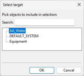
Opens a dialog for selecting all objects that use a specific system. |
|
|
|
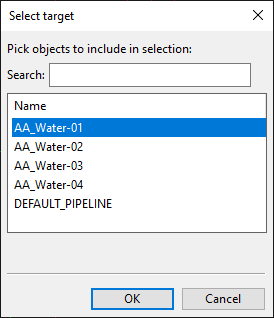
Opens a dialog for selecting all objects that use a specific line. |
|
|
|
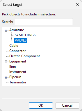
Opens a dialog for selecting all objects that represent a specific object type or object sub-type. |
|
|
Ctrl+V |
Pastes the contents of the clipboard into the active diagram. |
|
|
|
When enabled, selections can include drafting objects. |
|
|
|
When enabled, selections can include diagram objects. |
|
|
|
Opens the 2D-digitize menu. |
|
|
F6 |
Moves the cursor to the nearest grid point. |
|
|
F7 |
Shows or hides the grid. |
|
|
F8 |
Enables or disables cursor movements being restricted to orthogonal directions. Ortho is only applied to the cursor in relevant contexts, such as when moving a diagram object. |
|
|
F10 |
Opens the Grid, Snap & Cursor Step dialog. See Grid, Snap & Cursor step settings (F10). Snap is only applied to the cursor in relevant contexts, such as when moving a diagram object. |
|
|
Cancel |
Esc |
Cancels the context menu. |
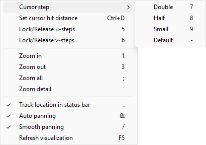
The 2D-digitize context menu includes the following commands.
|
Command |
Shortcut |
Description |
|---|---|---|
|
Cursor step > Double |
7 |
Increases cursor's step length by doubling the current step length. |
|
Cursor step > Half |
8 |
Decreases cursor's step length by halving the current step length. |
|
Cursor step > Small |
9 |
Applies predefined short step length to the cursor. |
|
Cursor step > Default |
- |
Applies predefined default step length to the cursor. |
|
Set cursor hit distance |
Ctrl+D |
Opens a dialog for defining the size of the cursor area used for picking objects (1–50).
|
|
Lock/Release u-steps |
5 |
Locks the cursor so that it cannot move in the X-direction and displays 'X-fixed' in the status bar, or releases the cursor if it was previously locked. |
|
Lock/Release v-steps |
6 |
Locks the cursor so that it cannot move in the Y-direction and displays 'Y-fixed' in the status bar, or releases the cursor if it was previously locked. |
|
Zoom in |
1 |
Zooms in on the diagram by halving the current display scale. |
|
Zoom out |
3 |
Zooms out of the diagram by doubling the current display scale. |
|
Zoom all |
; |
Fits the whole diagram into the diagram window. |
|
Zoom detail |
' |
Applies the Detail Scale defined in the User Interface settings to the diagram. |
|
Track location in status bar |
. |
Enables or disables the continuous display of the cursor coordinates in the status bar. |
|
Auto panning |
& |
Enables or disables automatic panning. If automatic panning is disabled, hold down the mouse wheel to pan. |
|
Smooth panning |
/ |
Enables or disables smoother panning movements when automatic panning is used. |
|
Refresh visualization |
F5 |
Refreshes the contents of the active diagram, for example if some drafting lines appear distorted after zooming. |

Context menu for one object
When a single diagram object is selected and there is no active command, right-clicking the diagram opens a context menu with the following commands.
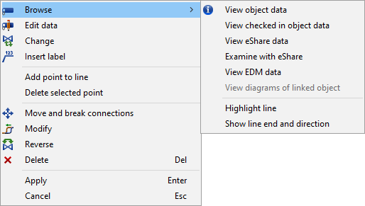
In the context menu of diagram objects, the main level can contain the following items. Object type determines which of these menu items are shown.
|
Command |
Shortcut |
Description |
Command in ribbon |
More information |
|---|---|---|---|---|
|
Browse |
|
Opens a submenu with the commands listed in Browse menu commands. |
— |
— |
|
Properties |
|
Displays the properties of the object in the Properties pane. |
Home > Show > Panes > Property Pane |
|
|
Edit system |
S |
Opens the system editor for editing the system of the object. |
Data > Identifiers > Systems and lines |
|
|
Edit line |
L |
Opens the line editor for editing the line of the object. |
Data > Identifiers > Systems and lines |
|
|
Visual properties |
|
Opens the visual properties of the object. |
— |
— |
|
Change |
|
Opens an object browser for selecting a different object template for the object. |
Home > Object > Change |
|
|
Insert label |
|
Inserts a default label to the selected object, if possible. |
Home > Label > Insert |
|
|
Add point to line |
|
Adds a control point to the selected connection line. |
— |
— |
|
Delete selected point |
|
Deletes the selected control point from the connection line. |
— |
— |
|
Add node point to equipment at cursor Add node point to object at cursor Add node point to symbol at cursor |
|
Adds a node to the selected object, to the point under the cursor. The user selects the node direction (0, 90, 180, 270) from the menu. |
Home > Node > Insert |
|
|
Modify node |
|
Opens the Node Properties dialog. |
Home > Node > Modify |
|
|
Delete node point at cursor |
|
Deletes the node point under the cursor, if possible. |
Home > Node > Delete |
|
|
Move |
|
Allows moving the object. The connection lines follow the object to the new location. |
Home > Modify > Move > Move |
|
|
Move and break connections |
|
Disconnects the object from connection lines and allows moving it to a different location. |
Home > Modify > Move > Move and break connections |
|
|
Copy without data |
|
Copies the selection without data to the clipboard. |
Home > Modify > Copy > Copy without data |
|
|
Copy with data |
|
Copies the selection with data to the clipboard. |
Home > Modify > Copy > Copy with data |
|
|
Copy to clipboard |
|
Copies the selection to the clipboard. |
Home > Modify > Copy > Copy to clipboard |
|
|
Reverse |
|
Reverses the flow direction of the object. |
Home > Modify > Reverse |
|
|
Mirror |
|
Mirrors the object across its centerline. |
Home > Modify > Mirror |
|
|
Delete |
Del |
Deletes the object. |
Home > Modify > Delete |
|
|
Apply |
Enter |
Applies the change. |
— |
— |
|
Cancel |
Esc |
Cancels the context menu. |
— |
— |
The Browse node of the context menu of diagram objects can contain the following commands.
|
Command |
Description |
Command in ribbon |
More information |
|---|---|---|---|
|
View data |
Shows the current data of the object in read-only mode. |
— |
— |
|
View checked in data View checked in object data |
Shows the latest checked-in data of the object in read-only mode. If you decide to cancel the check-out of the diagram, this is the data that the object will have. |
— |
— |
|
View eShare data |
If the position ID of the selected object is found in eShare, this command shows the eShare data of the object in a separate dialog. |
— |
|
|
Examine with eShare |
If the position ID of the selected object is found in eShare, this command opens eShare in the default web browser and shows the object in examination mode. Note: If the eShare project is configured to require eShare App, you can copy the address from the web browser and paste it into eShare App. |
— |
|
|
View EDM data |
Shows the EDM data of the object. |
— |
|
|
View diagrams of linked object |
Shows which diagrams contain objects that are linked to this object (by having the same position ID). |
— |
|
|
Highlight labels |
Highlights the label of the object. |
— |
— |
|
Highlight line |
Highlights the whole line of the selected object. The name of the highlighted line is displayed in the status bar. |
Data > Find > Highlight line |
|
|
Show line end and direction |
Highlights the pipe run, instrument line or cable as well as the object at each end of the line and shows a number to indicate where the head (1) and the tail (2) of the line are. |
— |
— |
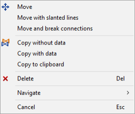
Context menu for multiple objects
When multiple diagram objects are selected and there is no active command, the context menu includes the following commands.
|
Command |
Shortcut |
Description |
Command in ribbon |
More information |
|---|---|---|---|---|
|
|
Allows moving the objects so that connection lines are re-routed to the new location using straight lines (right angles). |
Home > Modify > Move > Move |
||
|
|
Allows moving the objects so that connection lines are re-routed to the new location using slanted lines. |
Home > Modify > Move > Move with slanted lines |
||
|
|
Allows moving the objects so that connection lines are disconnected and do not follow the objects to the new location. |
Home > Modify > Move > Move and break connections |
||
|
|
Copies the selection without data to the clipboard. |
Home > Modify > Copy > Copy without data |
||
|
|
Copies the selection with data to the clipboard. |
Home > Modify > Copy > Copy with data |
||
|
|
Copies the selection to the clipboard. |
Home > Modify > Copy > Copy to clipboard |
||
|
Delete |
Del |
Deletes the objects. |
Home > Modify > Delete |
|
|
Navigate |
|
Opens a menu that contains the Grid on/off (F7) command. |
— |
— |
|
Cancel |
Esc |
Cancels the context menu. |
— |
— |
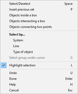
Context menu for selecting objects in commands
When using a command that requires objects to be selected, the context menu includes the following commands.
|
Command |
Shortcut |
Description |
|---|---|---|
|
Select/Deselect |
Space |
Selects the object under the cursor. |
|
Insert previous set |
P |
Re-selects a previously selected set of objects, if still possible. |
|
Objects inside a box |
|
Allows selecting objects that are partly or completely inside a rectangle defined by selecting two corner points. |
|
Objects intersecting a box |
|
Allows selecting objects that are completely inside a rectangle defined by selecting two corner points. |
|
Objects connecting two points |
|
Allows selecting diagram objects, connection lines, and connected labels along a route defined by selecting two connection points. There can be several possible routes between the selected points. In the Accept Route dialog, selecting Yes accepts the currently selected route, and selecting No tries to include additional routes in the selection. |
|
Select by… System |
|
Opens a dialog for selecting a system, and then allows the user to define a rectangle by selecting two corner points. Accepting the selection selects the objects that are completely inside the rectangle and use the given system. |
|
Select by… Line |
|
Opens a dialog for selecting a line, and then allows the user to define a rectangle by selecting two corner points. Accepting the selection selects the objects that are completely inside the rectangle and use the given line. |
|
Select by… Type of object |
|
Opens a dialog for selecting an object type or sub-type, and then allows the user to define a rectangle by selecting two corner points. Accepting the selection selects the objects that are completely inside the rectangle and represent the given object (sub-)type. |
|
Highlight selection |
L |
When this option is enabled, the objects that are selected in the active diagram are highlighted. |
|
Undo |
U |
Reverses the previous action. |
|
Done |
Enter |
Accepts the action. |
|
Cancel |
Esc |
Cancels the context menu. |