P&ID integration in 3D routing
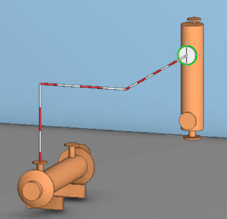
Using integration between Plant Modeller and P&ID allows the 3D design work to be assisted by information that is provided by P&I diagrams. The pipe routing tool shows the route from the current equipment to the target equipment/valve. If more than one pipeline connects to one piece of equipment, the Plant Modeller user must select the correct pipeline from a list of candidates. If the pipeline knows its start point and end point, the routing assistance bar shows the way to the correct equipment's center point.
Accurate routing assistance can be provided by using node level mappings. When there is name-based mapping between the nodes of the P&I diagram and the 3D model, the piping designer selects the node where the routing starts and the program automatically selects the correct pipeline. After this, if the pipeline is heading to a valve or equipment node, the routing assistance bar shows the way to the correct node.
Node-level routing assistance can be enabled in two ways:
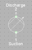
- Matching node names. This is useful when nodes commonly have the same functions so that the administrator can use the same names. For example, pumps usually have an 'in' node and an 'out' node, so they can be called, for example, 'Suction' and 'Discard' in all GDL component nodes and in the symbols that the diagram object templates use. If the component and its nodes are drawn first in P&ID, the P&ID user can name the nodes appropriately.
- Mapping in P&ID. The P&ID user can define node mappings before publishing to 3D. The P&ID user must select the component model to use. In this case, the node names do not need to match, but nominal sizes and flow directions must not be in conflict.
In Plant Modeller, the name-based routing significantly reduces the need to select pipelines and their target connections and greatly improves the quality of the piping design.
Important: P&ID integration in 3D routing is not available for diagrams that have been created by selecting 'Electric' or 'PFD' as the diagram type.
Setting up the environment for name-based routing assistance
Node names cannot contain special characters or empty spaces. Only letters Aa–Zz, numbers 0–9, and the underscore character '_' are accepted, and the first character must be a letter.
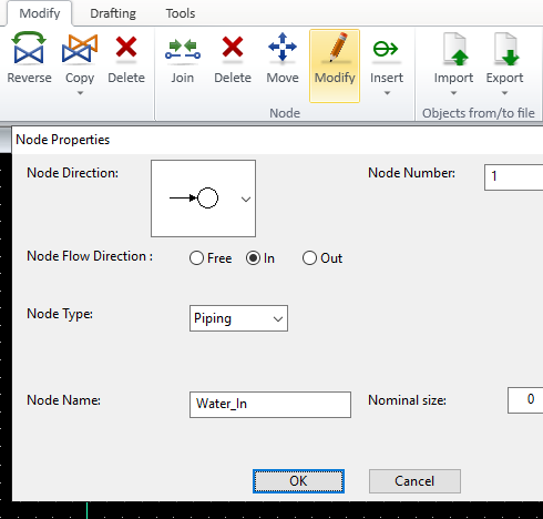
The node name of diagram objects can be defined already in the diagram symbol. Especially for simple cases such as IN/OUT and Suction/Discard, it is recommended to set matching names to the symbols. This can be done in the Node Properties dialog, which you can open with the Modify command.
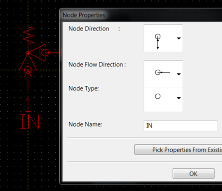
If the node name is defined in the diagram symbol, users cannot edit or replace it.
If the symbol name is coded in a script, the node function call must include the name, and the name must be in a valid format.
Example
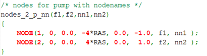
Using the CADMATIC example project, let's create a new node name function 'nodes_2_p_nn' by editing the symbol 'ISO_utils' in a text editor:
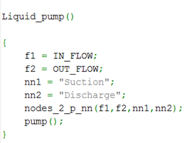
Then, for a valve where the nodes are to be named, we use this new node name function:
When object templates are inserted into a P&I diagram, the node names come from the symbol and are visible when the object is edited.
If the symbol names are changed, objects that already exist in the diagram will automatically get the new names.
Node names that are not defined in the symbol and nodes that are added in P&ID can be named and modified by the P&ID user by selecting the Modify tab > Modify.
Defining node names in the 3D model
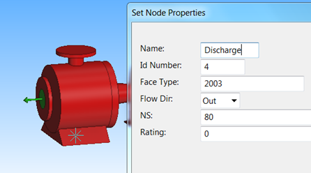
The node names of equipment and valves are defined in the Component Modeller application. Use descriptive node names, especially in the more complicated components that have several nodes, to make the mapping of nodes easier.
Mapping nodes between P&I diagram and the 3D model
P&ID users can create mappings between P&I diagram nodes and the 3D model. A diagram object can be linked to a component model stored in the library through the Data editor or the DmPartCode field in the Property Pane. The mapping tool reads the node information from the GDL and presents it together with the nodes from the P&ID object.

Note: If the object type is either Armature or Equipment, the node type must be 'Piping' or 'Generic'—the mapping tool ignores the other node types.
In this example, we do the mapping through the Edit Data dialog:
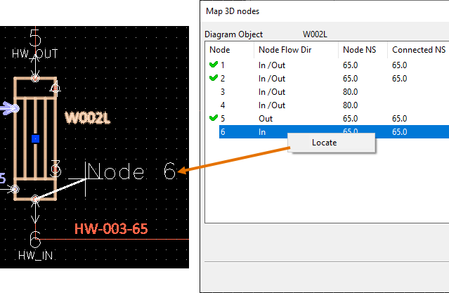
First, click Map to open the Map 3D Nodes dialog.
Then, to map the nodes, select one node row from the P&ID object (left side) and one row from the Catalog Part (right side), and then click Map.
- A new mapping is indicated with the asterisk sign (*).
- A component node that has been mapped is indicated with a green check mark
 .
. - One node cannot be mapped twice.
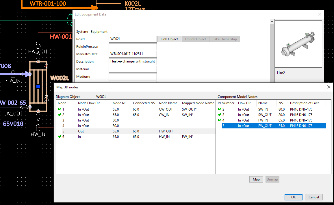
To make sure you are mapping the right nodes, pay attention to the nominal size of the node (if defined) and the nominal size of the connected object.
If you are not sure which node is which, you can right-click a node in the list and select Locate to show a large node number label and a rubber band line between the cursor and the node.
If there are wrong mappings, you can click Unmap to remove the selected mapping.
Note: Changing the symbol does not break the mapping as long as the node names and the flow directions do not change. Changing the component from the library (DmPartCode reference) does, however, break the mapping for those Mapped Node Names that cannot be found from the replacement component.
Auto-filtering of nodes when inserting a valve or instrument
When a 3D designer is inserting a P&ID linked Standard Component (valve, instrument) to the 3D model and uses the command Connect (P) or Insert Into line (L) to connect to an existing pipe node, Plant Modeller uses the topology network information provided by P&ID to figure out which node of the component to use for the connection.
The piping network information can be used in the insertion if the nodes of the diagram object have been manually mapped to those of the Catalog Part that the Standard Component uses (see Mapping nodes between P&I diagram and the 3D model) or if the program can identify the allowed nodes based on nominal size and flow direction.
This is how the automatic node matching functions:
-
The program compares the target node (connection point) in the 3D model to the nodes of the diagram object. Any diagram nodes that have a wrong nominal size, flow direction or (connected) pipeline are filtered out.
-
The program tries to find the target node from the piping network's topology. When connecting a valve to a pipe end, it tries to find a matching pipe from the diagram, and if the pipe is found it knows exactly which node to use. All the other nodes are filtered out.
-
The program performs normal model compatibility checks on the nodes.
-
After the above checks are done:
-
If 1 or more possible connection nodes are left, the inserting will use only those nodes.
-
If 0 possible nodes are left, and at least one node has been filtered out based on the piping network, a dialog opens to let the user select what to do:
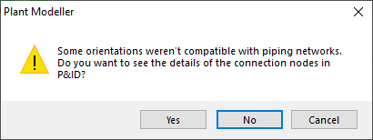
The choices are:
-
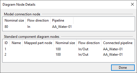
Yes – Opens the Diagram Node Details dialog, showing information about the target connection node and the diagram nodes of the component being inserted.
Using this information, the user should be able to figure out why the insertion was not allowed. In the example below, the nodes cannot be connected because the nominal sizes do not match. Clicking Done cancels the insertion.
-
No – Ignores the piping network information and inserts the component anyway.
-
Cancel – Cancels the insertion.
-
-