Node

On the Modify tab, the Node group contains tools for managing the nodes of the objects in the active diagram.
Connect

You can use the Connect command to connect the free node of a connection line to a diagram object or a branch to a main line. The maximum distance between the entities to be connected is 2 mm.
Unconnected nodes can occur, for example, when you route pipelines with the Automatic insert on/off (F5) context-menu option turned off.
Do the following:
-
Select the Modify tab > Node group > Connect.
-
Pick an unconnected line end that is located on a diagram object or a connection line and select Yes when prompted to confirm the action.
In the example below, the left image shows an unconnected node, and the right image shows the node after it has been joined.

-
Pick another node to be joined or press Esc to exit the tool.
Delete

You can delete free nodes.
Do the following:
-
Select the Modify tab > Node group > Delete.
-
Pick the free node to be removed.
-
Pick another node to be deleted or press Esc to exit the tool.
Move

You can move free nodes to a different location.
Do the following:
-
Select the Modify tab > Node group > Move.
-
Pick the node to be moved, and then pick the target location.
-
Pick another node to be moved or press Esc to exit the tool.
Modify

You can modify the properties of nodes. You can also modify nodes through the Connections tab of the Property pane.
Prerequisites
To set the node to display a 2D symbol, the symbol must meet the following requirements.
-
Symbol's default orientation is:
-
positive X for a nozzle symbol
-
positive Y for an actuator symbol
-
-
Symbol has at least one connection node.
-
Symbol's Type of node symbol attribute is set to either' Nozzle' or 'Actuator'.
-
Symbol's Show in 2D symbol menu attribute is set to 'Yes'.
Do the following:
-
Select the Modify tab > Node group > Modify.
-
Pick a node from the diagram. The Node Properties dialog opens.
-
Edit the node properties.
-
Node Direction – Select the direction of the connection line in relation to the node.
-
Node Number – Shows the node number.
-
Node Flow Direction – Select the flow direction: Free, In, Out
-
Node Type – Select the node type: Generic, Piping, Instrument, Electric
Note: Mapping to a component model requires this to be either "Generic" or "Piping".
 Show/hide example
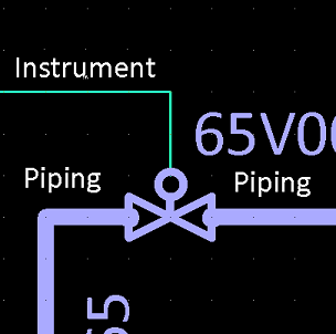
In the picture below, the valve symbol is connected to one instrument line and two pipelines. If the instrument line's node type is set to 'Instrument' and the piping network is released to 3D, only the specified kind of line can be connected to this node in the 3D model. However, if the node type is 'Generic' or 'Piping', the topology check interprets this as a three-way valve, thus allowing a pipe run to connect to the instrument line's node. The program automatically sets the node type when additional connection lines are drawn in diagrams, such as when an 'Iline' is connected to a valve.
-
Node Status – Shows whether the node is mapped to a node in the component model.
-
Node Name – Enter a name for the node.
-
Node Symbol – Select whether to use a node symbol: None, Other (click Select to select the symbol), Flange, Threaded
-
Nominal size from – Select from which NS field to take the nominal size, if there are several: NS, NS2, NS3…
Nominal size – Shows the currently selected NS field's nominal size.
-
Nominal size – Specify the nominal size of the node. For a mapped node, shows the nominal size in the component model.
Connected NS – Shows the nominal size of the connected object.
Properties for armature:
Properties for equipment:
-
- Select OK to accept the new settings.
- Press Enter if you want to pick another node to be modified.

Propagate

You can propagate the nominal size value of a given connection node onward along the connected pipe run. You can also use this command through the Connections tab of the Property pane.
The propagation process stops when it encounters one of the following:
-
An armature symbol where the node receiving the propagated value is the only node that is using the given nominal size field (NS, NS2, NS3…).
-
Equipment.
-
A cut in the pipe.
-
The end of the run (open end, connector, terminator).
Reducers and other parts with more than one NS size are automatically reversed if the propagation causes the previously smaller size to become the bigger size (or vice versa).
Tip: For armature, this command can also be run from an NS field of the Property pane, which will start the process from the specified node as well as from other nodes that use the same NS field.
Do the following:
-
Select the Modify tab > Node group > Propagate.
-
Move the cursor over the node from which to start the propagation process. The entities that will be affected are highlighted.
-
Click the node to propagate the nominal size of the node to the pipe run.
Insert
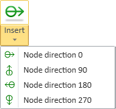
You can insert new free nodes to diagram objects.
Do the following:
- Select the Modify tab > Node group > Insert and then the required node direction: 0, 90, 180, 270.
- Pick the target location from an object.
- Insert another node or press Esc to exit the tool.