Nodes and connections
In P&I diagrams, 2D symbols and connection lines can be connected to each other via nodes. Nodes have properties, which allows the program to store important information about the connection, such as what is the nominal size of the connection. A node that is not connected to another diagram object is called a free node.
Connection nodes
In P&ID, most 2D symbols that are used as object templates have one or more nodes that define how the diagram object can be connected to other diagram objects.
In the template preview, connection nodes are shown as red circles that are either filled or empty, depending on the flow direction of the node:
- in – solid circle
- out – empty circle
- any – empty circle

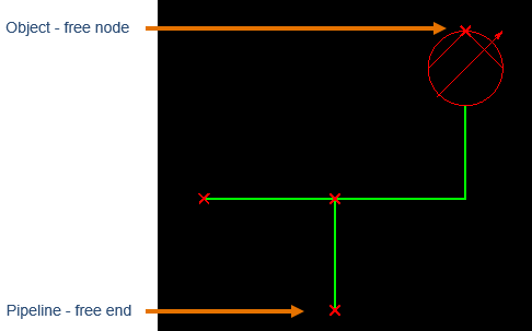
Free nodes
In diagrams, free (unconnected) nodes are displayed as a red X. Their visualization cannot be changed, but they can be hidden. Free nodes are not exported to diagram drawings.
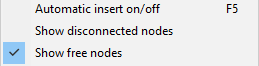
Free nodes are only intended to assist designers by showing all the available nodes. If free nodes are not wanted to be visualized, the project administrator can hide them permanently as described in Connections, or the designer can hide them in the current diagram editing session by disabling Show free nodes from the context menu.
Connected nodes
Established connections between diagram objects are shown as connected nodes, both on-screen and in exported drawings. The project administrator can define how a connected node looks, for example, when it connects a pipe run and an instrument, as described in Connections.
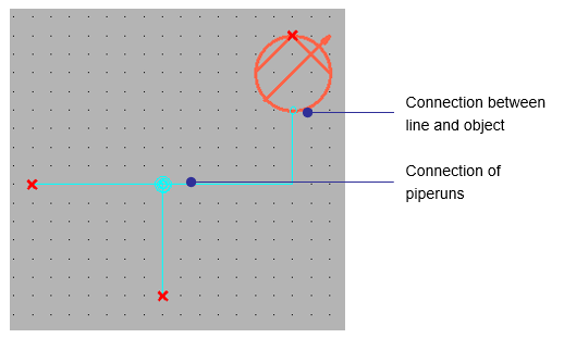
In the CADMATIC example project, the connection points are shown as follows:
-
Connection between an object and a line is shown with a circle, in the color of the system or line.
-
Connection between two lines is shown with a Connection point symbol.
-
Connection between two objects is not visualized.
Connection nodes in drawing a diagram line
-
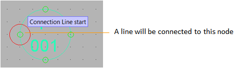
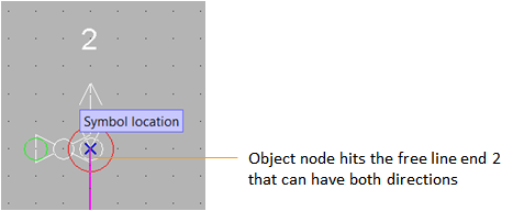
When inserting a connection line and the cursor is near a free node, the node displays its node number and flow direction.
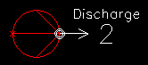
-
When a connection is about to hit a free node, a big red circle is drawn around the node.
-
When objects have been disconnected from each other, for example due to user performing an action such as Move and break connections, the disconnected nodes are shown with a circle and a cross.
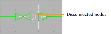
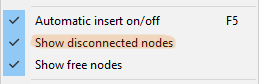
The designer can hide disconnected nodes in the current diagram editing session by disabling Show disconnected nodes from the context menu.
Connection nodes in inserting objects
-
Connection nodes are shown with medium-sized green circles when a user is inserting an object but has not confirmed the symbol location yet.
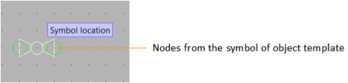
See Insert objects for more details on inserting objects.
Creating new connection nodes
Designers can create new connection nodes when drawing pipelines, circuits, or instrument lines. See Draw pipe runs.
Designers can add multiple new connection nodes that all have the same direction. On the Home tab, in the Node group, select Insert and then the required node direction, as described in Node.
Modifying and deleting connection nodes
The Home tab contains commands for managing connection nodes.
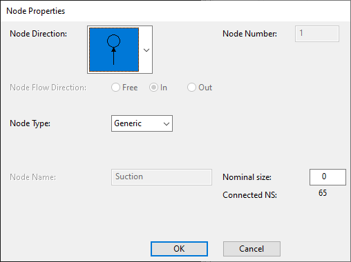
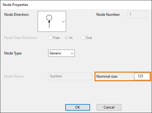
The Modify command opens the Node Properties dialog where you can edit properties such as flow direction and nominal size. Node Direction is set for nodes placed in Symbol Editor and it can't be edited when diagram is drawn.
The commands Delete, Move and Modify work on all nodes the same way, regardless of whether the node is coming from the object template symbol or created by the designer.
Note: The changes that are made here are only applied to the individual object in the diagram, not to the symbol of the object template. If the change should be made to the symbol of the object template, the administrator can do it in the symbol editor.
Nodes and nominal size
In the P&ID database, objects that are created under the ARMATURES main table normally have three Nominal Size fields in their sub-tables: NS, NS2, and NS3. These columns correspond with Catalog Part nodes in the 3D model.
A P&ID administrator can define how many different nominal sizes an ARMATURES sub-table can have. In the CADMATIC example project, Valves can have a maximum of three nominal sizes.
When a diagram contains an object that has multiple nominal sizes defined in the database, the designers can do the following:
-
Select how many nominal sizes to use in the object.
This can be done by selecting Edit data from the context menu of the object, and then adding or removing NS fields as needed.
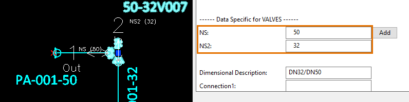
The picture below shows the Edit Armature Data dialog of a pressure release valve that has two NS fields and the option to add a third one.
-
Select which nominal size to use in each node of the object.
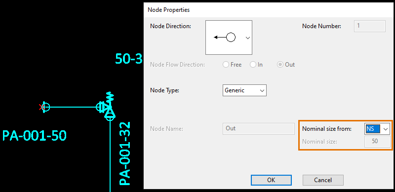
This can be done by selecting the Modify tool from the Node group of the Home tab, and then picking a node from the object. This opens the Node Properties dialog where the user can select from which NS field to take the nominal size value.
While armatures only support predefined nominal sizes, equipment allow the designer to set nominal size to any value.
In a connected node, the Node Properties dialog also shows the nominal size of the connected object.
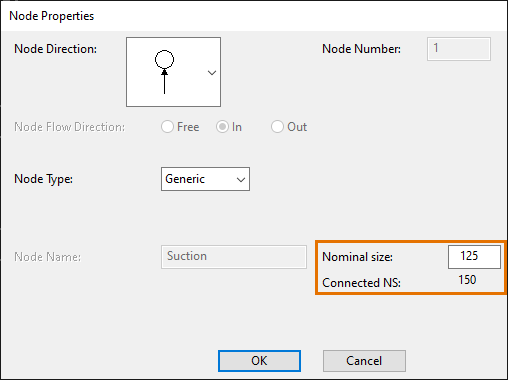
Tip: Data tab > Model group > Consistency check can report nodes whose nominal size does not match the nominal size of the connected object.
Nodes in 2D Symbol Editor
For example, the symbol of the basic non-return valve is defined so that there is a node at both ends, but flow direction is defined to be in at one end and out at the other. When you insert an object into a pipe run or instrument line, it is inserted according to the connection nodes 1 and 2.
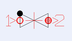
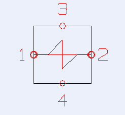
Symbols with two or four connection nodes
The cross (+) in the middle of the symbol is the origin.
The project administrator creates the nodes to the armature symbols when setting up the environment.
For vessels the project administrator cannot know in advance how many nodes will be needed. The P&ID application is built so that the user can create new connection points on the fly, whenever a new one is needed.