Creating isometric groups
To be able to create an isometric drawing, first you have to create an isometric group that contains a pipeline or a set of piping objects. You can define the isometric group using:
-
One System: one pipeline or a set of piping objects.
-
Several Systems: a set of piping objects or a block, System and pipeline.
Creating isometric groups for one pipeline
You can create an isometric group for one pipeline in the selected System. If the pipeline is too large for a single drawing, you can split the pipeline into multiple groups.
Prerequisites
-
All the relates objects are checked out to you, and they are not members of another isometric group.
Do the following:
-
On the Documents tab of Plant Modeller, click Piping Isometrics.
-
In the Piping Isometrics dialog, click the Select button or clear the option Several Systems to open the Select System dialog.
-
Select the required System from the list, and click OK.
-
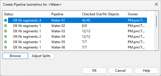
Select Groups > Create pipeline isometrics. The Create Pipeline Isometrics for <System> dialog opens, listing the pipelines of the selected System.
-
Select the required pipeline from the list. A separate view opens, showing a preview of the selected pipeline.
-
You can click Browse to browse the pipeline in a view. Press Esc to return to the Piping Isometrics dialog.
-
You can click Adjust Splits to split the pipeline into several isometric groups, if a single group would not fit comfortably into a single drawing.
-
Click OK. The new isometric group or groups are listed in the Piping Isometrics dialog, and you can create drawings for them.
Creating isometric groups for piping objects in one system
You can create an isometric group for a set of piping objects that use the same System.
Prerequisites
-
All the relates objects are checked out to you, and they are not members of another isometric group.
Do the following:
-
On the Documents tab of Plant Modeller, click Piping Isometrics.
-
In the Piping Isometrics dialog, click the Select button or clear the option Several Systems to open the Select System dialog.
-
Select the required System from the list, and click OK.
-
Select Groups > Create isometric, enter a name for the isometric drawing, and click OK. A separate view opens, indicating that there are no objects in the isometric group yet.
-
Define the members of the group:
-
To add objects into the group, select the group and then Modify > Assign objects.
Select the objects you want to add, and press Enter to add them.
-
To remove objects from the group, select the group and then Modify > Deassign objects.
Select the objects you want to remove, and press Enter to remove them.
-
-
The new isometric group is listed in the Piping Isometrics dialog, and you can create a drawing for it.
Creating isometric groups for piping objects in multiple systems
You can create an isometric group for a set of piping objects that use different Systems.
Prerequisites
-
All the relates objects are checked out to you, and they are not members of another isometric group.
Do the following:
-
On the Documents tab of Plant Modeller, click Piping Isometrics.
-
In the Piping Isometrics dialog, select the option Several Systems.
-
Select Groups > Create isometric, enter a name for the new drawing, and click OK. The new isometric group is listed in the Piping Isometrics dialog, and a separate view opens, indicating that there are no objects in the isometric group yet.
-
Define the members of the group:
-
To add objects into the group, select the group and then Modify > Assign objects.
Select the objects you want to add, and press Enter to add them.
-
To remove objects from the group, select the group and then Modify > Deassign objects.
Select the objects you want to remove, and press Enter to remove them.
-
-
The new isometric group is listed in the Piping Isometrics dialog, and you can create a drawing for it.
Creating isometric groups via containment, system and pipeline
You can create isometric groups for objects that belong to a containment in the 3D model. This means that the containment hierarchy, such as blocks and named spaces, can be used to define the contents of isometric drawings. See also Adjusting automatic arrangement of isometric groups.
Prerequisites
-
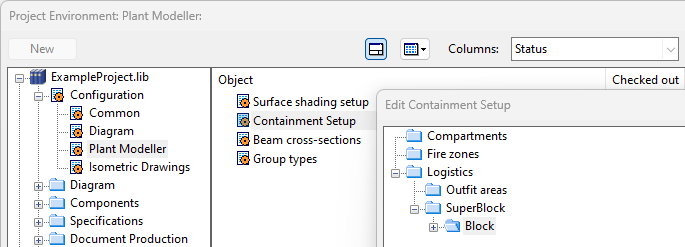
Administrator has created the containment configuration in File > Environment > All Library and Project > [library] > Configuration > Plant Modeller > Containment Setup, and containments have been defined in the 3D model. Both logistics (e.g. blocks) and non-logistics containment (e.g. compartments) can be used to generate containment-based piping isometrics and spools.
-
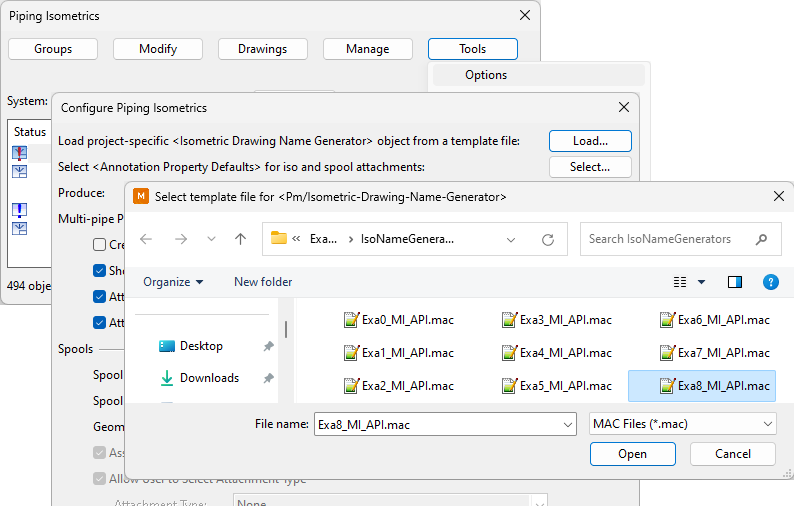
In the settings of the Piping Isometrics tool, you have loaded an Isometric Drawing Name Generator that supports containment-based isometrics and spools. There is an example file "Exa8_MI_API.mac" which you can select from Tools > Options > Load.
Do the following:
-
On the Documents tab of Plant Modeller, click Piping Isometrics.
-
In the Piping Isometrics dialog, make sure that the option Several Systems is selected.
-
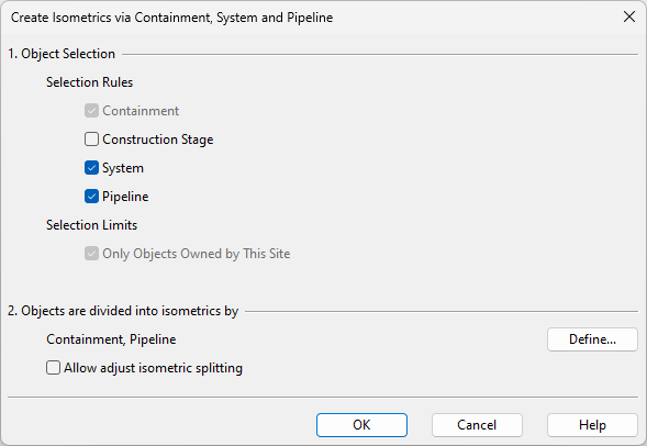
Select Groups > Create isometrics via containment, system and pipeline.
-
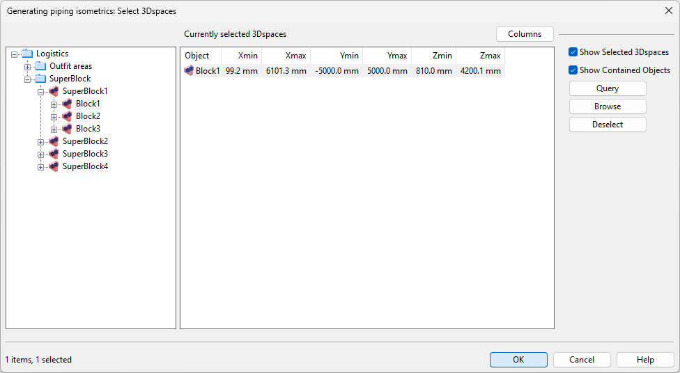
Define the settings for creating isometrics, and click OK. The Generating piping isometrics dialog opens.
-
Select the containment that contains the required piping objects, and click OK.