Start using Piping Isometrics & Spools
Piping Isometrics & Spools can create isometric drawings for piping parts that have been assigned to an isometric group in the 3D model. To define an isometric group, the 3D designer can select a set of piping parts or a whole pipeline into the isometric group, as required. One pipeline can only be a member in one isometric group. For more information, see Isometric groups.
Piping Isometrics & Spools can create spool drawings for piping parts that have been assigned to a spool. A pipe spool contains a set of connected piping parts that are prefabricated as a single unit. The project administrator defines the rules that automatically generate spools from the piping geometry in the 3D model. Large piping systems can be split into smaller pieces for visual purposes, to bring out the annotations. For more information, see Spools.
Presets by administrator
The following tasks should be done before the administrator starts to define the settings for contents, appearance, and configuration of isometric and spool drawings:
-
Administrator ensures that there is an ICGD and a Sheet available for both isometric and spool drawings in the project database.
-
Administrator ensures that the project database contains the property tags, symbols, and labels that are needed for annotating the isometric and spool drawings.
-
Administrator creates an area for Piping Isometrics & Spools in the CADMATIC desktop.
The general process of creating piping isometrics and/or spool drawings is as follows:
-
Step 1: Administrator defines globally the contents and the appearance of isometric and spool drawings in the project.
-
Step 2: Administrator defines globally how to produce isometrics and spools.
-
Step 3: Designer creates the isometric groups in Plant Modeller.
-
Step 4: Designer creates the isometric and spool drawings and runs automatic annotation.
-
Step 5: Piping Isometrics & Spools is used to browse and inspect the drawings.
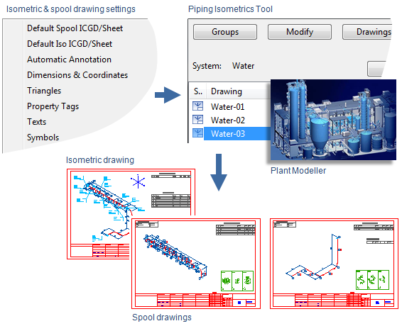
Step 1: Define global settings for drawings
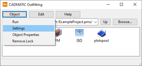
To define the global settings for the appearance of drawings, administrator selects the application icon in the CADMATIC desktop and then Object > Settings.
These are some of the settings:
-
Select an ICGD and a drawing sheet for both isometric and spool drawings.
-
Define the settings for automatic annotation.
-
Define the appearance of property labels, dimensions, etc.
-
Select the placement for attachments.
-
Select the drafting style.
The settings must be saved to the project database.
For more information, see Settings for Piping Isometrics & Spools.
Step 2: Configure piping isometrics
To automatically name the drawings and break the spools and long isometrics, the administrator configures the production of drawings using the piping isometrics tools in Plant Modeller.
These are some of the actions:
-
To load project specific naming rules for isometric and spool drawings.
-
To select which to produce: isometric or/and spool drawings.
-
To define the automatic breaking rules for spools.
-
To define the automatic breaking rules for isometrics.
For more information, see Configure Piping Isometrics.
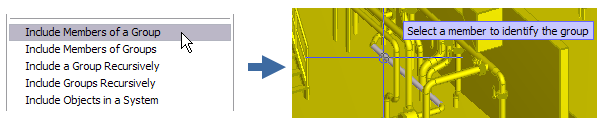
Step 3: Create isometric groups
Designer creates the isometric groups using the piping isometrics tools in Plant Modeller. First the designer has to check out the pipelines to have the rights to create groups for them. To clarify the status of pipelines, use the shortcut key Alt+5 to set the color of objects by owner. Green objects are checked out by you, yellow objects are checked in, and red objects are checked out by someone else. Press Alt+6 to restore the default colors.
Note: It is important to load updates to your design area before starting the piping isometrics tools, because designers might have made changes to pipelines in other design areas and in other sites. Do not create an isometric drawing of an unfinished pipeline.
-
Check out the pipeline and piping objects you want to add in an isometric group using the command Model > Check out. To select the whole pipeline, right-click a work view and select the command Select by group to select the correct group (=pipeline) from the list.
-
Click Documents > Piping Isometrics.
-
Click Select to change the system. Option Several Systems must be cleared.
-
Click Groups > Create pipeline isometrics.
-
Select the pipeline from the list. Names for the drawing and the group are generated automatically.
For more information, see Isometric groups.
Step 4: Create isometric and spool drawings
Next the designer creates the isometric and spool drawings and selects options:
-
Annotate, automatically annotates the drawing according to project settings.
-
Preview, shows a preview of the isometric drawing.
-
Plot, plots the drawing into a default printer.
-
Export, save the drawing as dxf etc. format according to the presets.
-
Attachment, attach a real view of the pipeline or spool in the isometric drawing.
Tip: You can also double-click an isometric group in the list to generate isometric and spool drawings with predefined actions.
Step 5: Manage drawings in Piping Isometrics & Spools
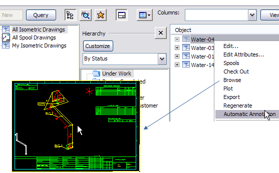
You can start the Piping Isometrics & Spools application from the Piping Isometric tool to work with drawings using command Documents > Piping Isometrics > Drawings > Work with isometric drawings or you can double-click the isometric drawing icon in the CADMATIC desktop.
When you have started Piping Isometrics & Spools, the browser for isometric drawings comes up. You can handle the selected drawing (right-click for context menu) automatically and browse the result. Annotations and sheet are set up by administrator, designer is not supposed to annotate the drawing.