Tools tab
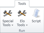
The Tools tab of the document editor includes the following tools.
Special tools

On the Tools tab, the Special tools menu includes the following tools.
Create cable fill rate view into drawing | Add XYZ axis markers into views | Mark named XY-coordinates into view | Module lines into view | Module line settings
Create cable fill rate view into drawing
You can create a cable fill rate view and add it to the active page.
Prerequisites
-
To complete this procedure, the cable router settings must define which annotation properties to use in cable drawings. See Drawing.
Do the following:
-
Open the document page where you want the fill rate view to be inserted.
-
Select Tools tab > Special tools > Create cable fill rate view into drawing. The active work view opens.
-
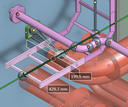
Select a cable network segment or a cable way object (a straight cable tray part or a cable penetration with sealing module) from the 3D model. Then press Enter to accept the selection.
 Show/hide image
In this example we select a straight cable tray part that is used by several cable network segments.

-
If you selected a cable way object and it contains multiple segments, the cursor locks to the centerline of the object.
Pick the location that you want to show in the fill rate view.
-
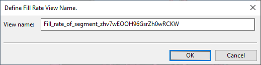
The Define Fill Rate View Name dialog opens.
Enter a descriptive name for the fill rate view, and click OK.
-
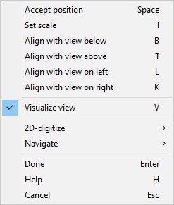
The document reopens and the fill rate view is attached to the cursor. You can now move the fill rate view to the intended location on the page.
-
You can right-click the page to access commands that allow you to change the scale or to align the fill rate view with another view on the page.
Tip: You can also rescale and move the fill rate view later, as described in Set scale and Move.
-
Click or press Enter to accept the location of the fill rate view.
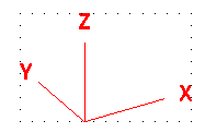
Add XYZ axis markers into views
You can insert a marker that shows the main axis directions of a drawing view.
Do the following:
-
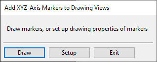
Select Tools tab > Special tools > Add XYZ axis markers into views. A selection dialog opens.
-
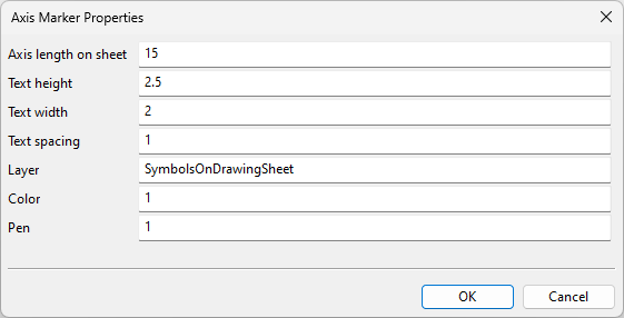
If this is the first time you are using this tool or you want to modify the current settings, click Setup, define the following settings, and click OK.
Tip: Layer can be set using either the Layer Id from Drawing export configuration or the layer name which is also available in Layer configuration.
-
Insert the axis marker:
-
Click Draw.
-
Select the target view from the list and click OK.
-
Move the cursor to the intended location of the axis marker and pick that location.
-
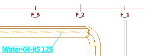
Mark named XY-coordinates into view
You can show the reference planes (named coordinates) of the 3D model, such as frame borders or the center line, by drawing a marker line of desired length into a drawing view. In the tool's settings you can define the visual properties of the marker.
For information on administrating named coordinates, see Coordinate references.
Do the following:
-
Select Tools tab > Special tools > Mark named XY-coordinates into view. A dialog opens, listing the views on the current page.
-
Select the target view from the list and click OK. The settings dialog opens.
-
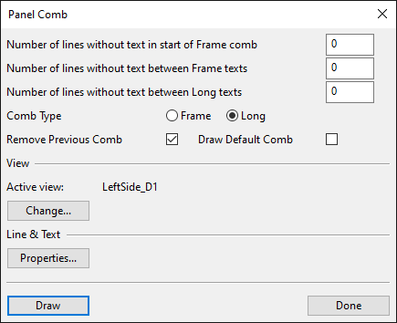
Define the following settings.
-
Number of lines without text in start of Frame comb – Specifies how many frame borders should not be labeled at the beginning of the marker.
-
Number of lines without text between Frame texts – Specifies how many frame borders should not be labeled after each labeled frame border.
-
Number of lines without text between Long texts – Specifies how many longitudinal lines should not be labeled after each labeled line.
-
Comb Type – Select Frame to draw a marker for frame borders or Long to draw a marker for longitudinal lines.
-
Remove Previous Comb – If selected, drawing a new marker will automatically remove the previously drawn marker.
-
Draw Default Comb – If selected, the marker will be drawn with default settings.
-
Active view – Click Change if you want to change the target view.
-
Line & Text – Click Properties if you want to change the line or text properties of the marker to be drawn.
-
-
Click Draw.
-
Pick the start point and the end point of the marker line.
-
Click Done.
Module lines into view
You can show the reference planes (named coordinates) of the 3D model by drawing a marker line of desired length into a drawing view. In the tool's settings you can define the visual properties of the marker.
For information on administrating named coordinates, see Coordinate references.
Prerequisites
-
You have defined the visual properties of the marker, as described in Module line settings.
Do the following:
-
Select Tools tab > Special tools > Module lines into view. A dialog opens, listing the views on the current page.
-
Select the target view from the list.
-
Pick the start point and the end point of the marker line.
Module line settings
You can define the visual properties and the layer assignment of module lines.
Do the following:
-
Select Tools tab > Special tools > Module line settings. The settings dialog opens.
-
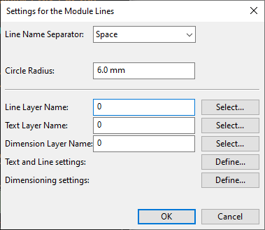
Define the following settings.
-
Line Name Separator – Select which of the following to use as the line name separator: space, no separator, a user-defined character.
-
Circle Radius – Specify the radius of the circle that shows the line name (millimeters).
-
Line Layer Name – Click Select to select the layer to use for the line patterns.
-
Text Layer Name – Click Select to select the layer to use for the label texts.
-
Dimension Layer Name – Click Select to select the layer to use for the dimensions.
-
Text and Line settings – Click Define to define the visual properties of the lines and the texts.
Show/hide image
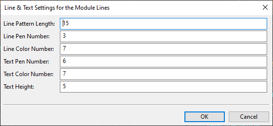
Click OK to accept the new settings.
-
Dimensioning settings – Click Define to define the visual properties of the dimensions.
Show/hide image
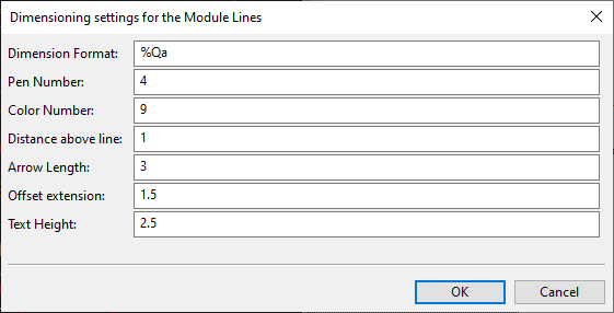
Click OK to accept the new settings.
-
-
Click OK. You can now draw module line markers with the given settings, as described in Module lines into view.
Elo tools

On the Tools tab, the Elo tools button is displayed if the EloTools option was selected when installing CADMATIC and includes the following tools.
Equipment centerlines | Pipe hiding box | Support pipeline list | Support visualizer | Equipment centerline settings | Support pipeline settings | Support spools settings | Stub-in drawing development
Equipment centerlines
You can add centerlines to all equipment in a drawing view.
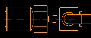
Do the following:
-
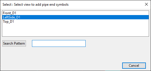
Select Tools tab > Elo tools > Equipment centerlines. The Select : Select view to add pipe end symbols dialog opens, listing the drawing views on the active page.
-
Click the name of the intended view.
-
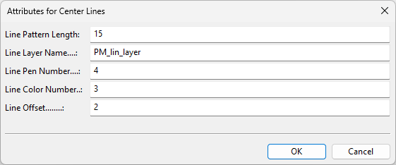
If this is the first time you are running this tool, the Attributes for Center Lines dialog opens.
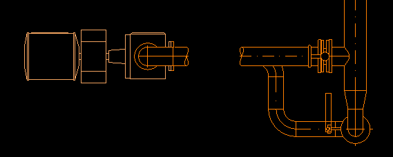
Define the visual properties of the centerlines, and then click OK.
Later on, you can modify the settings as described in Equipment centerline settings.
Pipe hiding box
You can set a part of a pipe to be hidden in a drawing view.
Do the following:
-
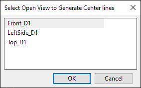
Select Tools tab > Elo tools > Pipe hiding box. The Select Open View to Generate Center lines dialog opens, listing the drawing views on the active page.
-
Select the intended view and click OK.
-
Pick the pipe object and press Enter. The middle part of the pipe is hidden and the cursor is constrained to the centerline.
-
Pick the point where you want the hiding box to start.
-
Pick the point where you want the hiding box to end.
-
Press Enter to exit the tool.
-
Regenerate the drawing view as described in Regenerate. The pipe segment that is inside the hiding box is now hidden.
Support pipeline list
Support visualizer
Equipment centerline settings
Select Tools tab > Elo tools > Equipment centerline settings to open the Attributes for Center Lines dialog where you can define the line properties of the centerlines you generate with the Equipment centerlines tool.
-
Line Pattern Length – Specify the pattern length (5–30).
-
Line Layer Name – Specify the name of the layer to use for the lines. You can check the available layer names from the Layer configuration.
-
Line Pen Number – Specify the number of the pen to use for the lines (1–10).
-
Line Color Number – Specify the index number of the color to use for the lines (1–50).
-
Line Offset – Specify the offset of the lines (0.5–5).
Support pipeline settings
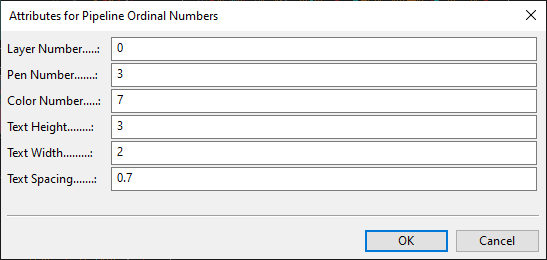
Select Tools tab > Elo tools > Support pipeline settings to open the Attributes for Pipeline Ordinal Numbers dialog where you can define the line properties of pipelines in support drawings.
Support spools settings
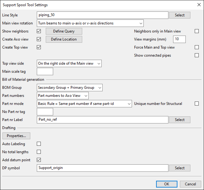
Select Tools tab > Elo tools > Support spools settings to open the Support Spool Tool Settings dialog where you can define settings for support drawings. See Define settings for support spool tool.
Stub-in drawing development
Script

Select Tools tab > Script to run a Plant Modeller script file (.mac, .bs).