Drawings
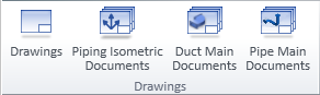
On the Documents tab, the Drawings group contains tools for managing different types of drawings. Administrator defines the visibility of some of these buttons in File > Options > Shared Settings > Documents, as described below.
-
Drawings opens a document object browser for managing Plant Modeller drawings.
-
Piping Isometric Documents (new method) opens a document object browser for managing piping isometric documents that have been created on the Piping Isometric tab of Plant Modeller.
Note: The button is shown if Isometric tool in use is set to New integrated tool in the Isometric Drawing options.
-
Piping Isometrics (old method) opens a dialog for managing the pipe spools that are used in piping isometric drawings created in the Piping Isometrics & Spools application.
Note: The button is shown if Isometric tool in use is set to Older tool with separate PI&S area in the Isometric Drawing options.
-
Duct Main Documents opens a document object browser for managing duct spool drawings.
-
Pipe Main Documents opens a document object browser for managing pipe spool drawings created on the Pipe Spools tab.
Note: The button is shown if Use pipe spool drawings is selected in the Pipe Spool Drawing options.
For more information on the document object browser, see Document browser.
For more information on the document editor, see Document editor.
CADMATIC uses the following terminology to describe the structure of documents:
-
Drawing – Consists of one or more pages. You can plot drawings and export them into data formats understood by other CAD programs.
-
Page – You can add, modify and delete pages. You can select which drawing sheet to use on each page.
-
Sheet – Framed area that contains the title block, views extracted from the 3D model, and annotations.
Note: Normally, the sheet to use must be approved for use in the project. However, when you create a drawing and select the ICGD, the sheet to be used is the primary sheet defined in the ICGD. Thus, sheets used for one-page drawings do not have to be approved for the project—it is enough that the ICGD has been approved.
The picture below shows the main building blocks of a drawing (drawing sheet, drawing views, annotations, Bill of Materials) and which settings affect each.
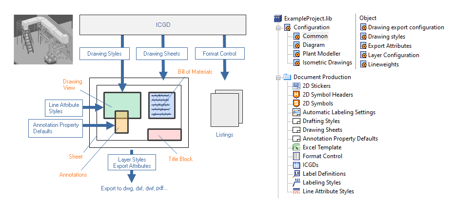
Before you can create drawings, administrator must specify the required settings, as described in Administrating document production. Below is a summary of what the different settings do.
Configuration > Common
-
Drawing Styles – Defines the text styles, dimension styles and linetypes for annotations. See Drawing styles.
-
Export Attributes – Defines which attributes to assign to blocks in DWG or PDF export. For example, a block that consists of a valve can have Nominal Size, Valve Position Id and Pipeline Id as attributes. See Export attributes.
-
Layer Configuration – Defines the layers to which objects can be assigned when drawing is exported. Each layer can be associated with a color, linetype and lineweight, and annotations can inherit these properties from the layer they are assigned to. See Layer configuration.
-
Lineweights – Defines an index number for each lineweight that can be used in drawings. The index number can be referenced, for example, by a 2D symbol or a drawing sheet. See Lineweights.
Document Production
-
ICGDs – An ICGD defines which drawing sheet to use and what kind of content to show in Bill of Materials (BOM) or in other kinds of listings. See ICGDs.
-
Drawing Sheets – Defines the drawing sheets that can be used for drawings. The configuration specifies the sheet size, the margins, the frames, the title block, and the position and the visual properties of the BOM. See Drawing Sheets.
-
Annotation Property Defaults – Defines the default properties such as color, linetype, text height and layer for the different annotation types: text, polyline, arc, circle, hatch, dimension, spline, symbol, section marker, and revision cloud. These default properties can utilize the styles defined in the Drawing Styles configuration or be separately configured.
Administrator can create separate defaults for different kinds of use cases. When a designer starts the annotation tool, the program loads the defaults that were used last, but the designer can switch to another annotation style, if appropriate. This encourages all the designers to use the same set of properties, and the benefit is that the different document types have a unified look across the project. See Annotation Property Defaults.
-
Format Control – Defines the properties of listings shown in drawings. See Format Control.
-
Label Definitions – Defines how to combine a 2D symbol with attribute information from a 3D object. See Label Definitions.
-
Layer Style – Defines how to assign objects to layers when drawing is exported.
-
Line Attribute Styles – Defines the visual properties of the lines used to draw model objects in drawing views. For example, the centerline of pipelines can be visualized as a dashed line. See Select line attribute style.