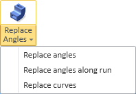
Replace angles
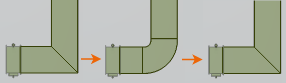
You can replace a mitered joint with a curved duct component or a curved duct component with a mitered joint.
Replace angles
You can replace a mitered joint of two connected duct parts with a curved duct component.
Do the following:
-
Select Ducting tab > Duct parts group > Replace angles > Replace angles.
-
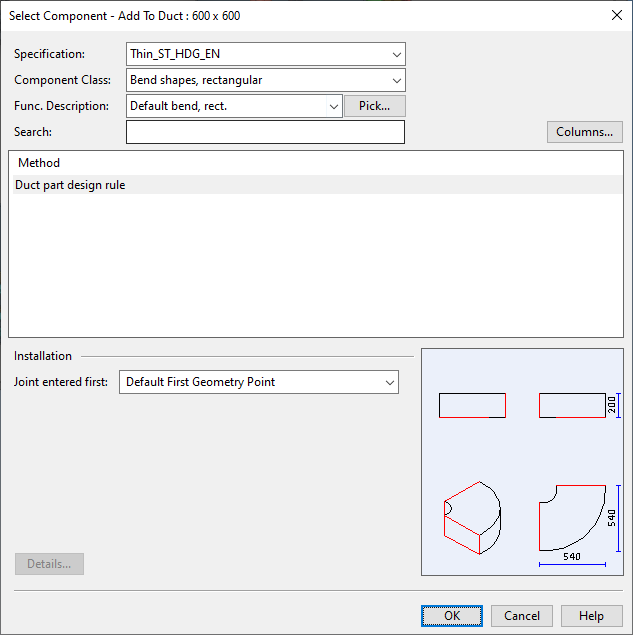
Move the cursor near the mitered joint, so that the connection point becomes highlighted, and click or press Space to accept the point. The Select Component – Add To Duct dialog opens.
-
Define the properties of the part:
-
Specification – Select the specification.
-
Component Class – Select the component class.
-
Functional Description – Select the functional description.
-
Method or Size (if out-of-spec component)
-
Joint entered first – Select which joint (connection point) of the component to use as the starting point. This defines the orientation of the component in the model, but you can also correct the orientation afterward, if needed.
-
Details – Select this to add attributes to the component.
Then click OK.
-
-
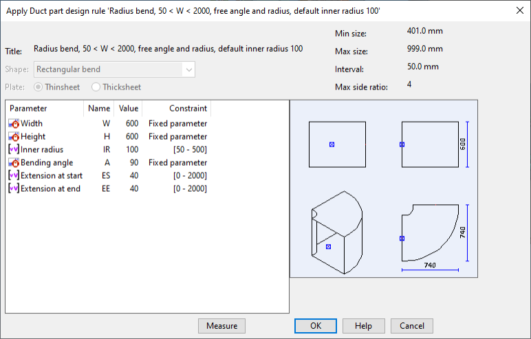
'Apply Duct part design rule' dialog opens.
You can edit the shape parameters that do not display a lock icon by double-clicking the parameter row; see 'Edit value of shape parameter' dialog for details. Click OK to continue.
- If the part uses instance parameters, the Edit Instance Parameters dialog opens for setting the values. See Size of part for details. Click OK to continue.
-
The mitered joint has now been replaced with a curve. You can continue replacing other mitered joints in the same way or press Esc to exit the tool.
Replace angles along run
You can replace all mitered joints along a duct run with a curved duct component.
Do the following:
-
Select Ducting tab > Duct parts group > Replace angles > Replace angles along run.
-
Select a set of connected duct parts and press Enter. The Select Component – Add To Duct dialog opens for replacing the first mitered joint along the run.
-
Define the properties of the part:
-
Specification – Select the specification.
-
Component Class – Select the component class.
-
Functional Description – Select the functional description.
-
Method or Size (if out-of-spec component)
-
Joint entered first – Select which joint (connection point) of the component to use as the starting point. This defines the orientation of the component in the model, but you can also correct the orientation afterward, if needed.
-
Details – Select this to add attributes to the component.
Then click OK.
-
-
'Apply Duct part design rule' dialog opens.
You can edit the shape parameters that do not display a lock icon by double-clicking the parameter row; see 'Edit value of shape parameter' dialog for details. Click OK to continue.
-
If the part uses instance parameters, the Edit Instance Parameters dialog opens for setting the values. See Size of part for details. Click OK to continue.
-
The first mitered joint has now been replaced with a curve. Continue replacing each additional mitered joint along the duct line in the same way.
Replace curves
You can replace a curved duct component with a mitered joint.
Do the following:
-
Select Ducting tab > Duct parts group > Replace angles > Replace curves.
-
Click a curved duct component and press Enter. The curve is replaced with a mitered joint.
-
You can continue replacing other curves in the same way or press Esc to exit the tool.