Routing
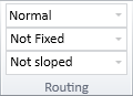
On the Piping tab, the Routing group defines settings for automatic pipe routing.
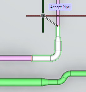
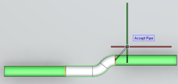
Selecting Automatic routing (R) during pipe routing tries to automatically route the pipe to the current cursor location. The original direction of the pipe is applied also to the end of the automatically routed segment, except if the target point was defined with constrained direction, then routing will continue in the constrained direction. If connecting to a pipe of different size, auto-routing automatically inserts a reducer.
-
Method for auto routing – Select the auto-routing method to use.
-
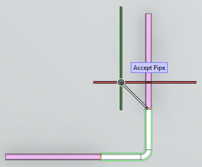
Normal – Tries to find a route using only the main axis directions except if the route starts from or ends at a connected pipe that is not main axis aligned, then also the direction of the connected pipe is accepted. (This method might find a route also in cases where the other methods cannot find one.)
-
Shortest Distance – Tries to find the shortest route using default curves or curves that are set as active.
-
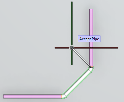
Two Curves – Tries to find a route using only the main axis directions, except if there is not enough space for that, then it inserts two consecutive curves to the route.
-
-
Flexible curves – Not Fixed, 15°, 30°, 45°, 60°, or a user-defined angle (type the value in the field and press Enter).
-
Slope for routing – Not sloped, ±1/100, ±1/50 or ±1/20. This setting is applied when routing a pipe in the XY-plane and using the direction wheel to select the routing direction. Also selectable from the pipe routing context menu: Slope. The default values are defined in the shared project settings, as described in Routing.
Best fitting elbow principle
When a curve is being inserted or modified, the program selects the best fitting part from the elbow parts defined in the piping specification. Among the possible candidates, the best fitting part exceeds the intended angle by the smallest amount, and in the case of modifying an existing curve, its following properties are the same as those of the existing part:
-
curvature
-
wall thickness
-
material and standard
-
connection types
To enable the program to find a fitting part in each case, piping specifications can use the following Short Codes to define parts that have different maximum angles:
-
e
-
el75
-
el60
-
el2
-
el45
-
el30
-
el15
Example
The piping specification defines four flexible elbows:
-
Short Code 'e' with a max angle of 93°.
-
Short Code 'el75' with a max angle of 76°.
-
Short Code 'el60' with a max angle of 61° and wall thickness that is different than in the other parts.
-
Short Code 'el45' with a max angle of 46°.
The 3D model contains a 90° elbow (Short Code 'e'), but then a piping designer makes a modeling change that requires the existing elbow to be replaced by a 50° elbow. The program starts searching the specification for the best fitting elbow: 'el45' is not curved enough, 'el60' has the least amount of excess (10°) but wrong wall thickness, so the program chooses the 'el75' elbow.