Pipe routing context menu
When routing a pipe, right-clicking the work view opens a context menu where you can select the following commands.
|
Command |
Shortcut |
Description |
|---|---|---|
|
Space |
Routes a pipe from the previous route point to the current cursor location. |
|
|
Insert |
See Add components. |
|
|
|
Opens the following menu:
See Branches. |
|
|
|
Creates a mitered pipe joint at the current cursor position. When you are routing a new pipe segment and have navigated to the point where the pipe is to change direction, selecting the Create Miter command completes the pipe segment up to the miter joint and allows you to define the miter angle by selecting the new direction of the pipe. See also Join with miter. |
|
|
P |
See Connect pipes. |
|
|
J |
See Connect pipes. |
|
|
|
Ends the pipe routing and marks the connection node at the end of the pipe as terminated. The continuity check treats a terminated pipe in the same way as a connected pipe. If you try to connect to a terminated node, you are prompted to remove the terminator mark. |
|
|
Ctrl+F |
Allows the new pipe to be routed by following the route of an existing pipe. See Follow pipe. |
|
|
M |
Tries to route the pipe to the digitized point. |
|
|
Ctrl+A |
Opens the Grid Based Automatic Routing dialog. |
|
|
L |
Inserts a curve at the current location, allowing the routing of a straight pipe to continue. |
|
|
O |
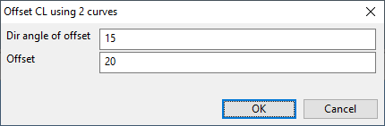
Opens the Offset CL using 2 curves dialog where you can define an offset from the current pipe centerline.
When you click OK, the offset is created by placing two curves, and you can continue the routing from the second curve onward. Note that if the current functional description designates that curves are bent by a machine, a straight pipe piece is added between the two curves. The length of this straight pipe piece is the minimum distance between bends that the machine requires, so that the pipe does not need to be cut before the bending. |
|
|
Shift+K |
Adds a new straight piece of pipe or stretches the last one so that the cut length (including bends and extra lengths) consumes the entire delivered pipe length. The length of the delivered pipe can be specified in the corporate catalog or the dimension table through the 'DPL' tag. If this tag is not set, then the value defined in the Routing options is used. If this value is not set, a default value of 6,000 mm is applied. |
|
|
|
Opens the following menu:
|
|
|
|
Opens the following menu:
|
|
|
|
Opens the following menu:
See Routing. |
|
|
|
Opens the following menu:
|
|
|
|
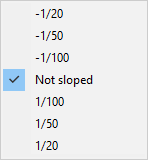
Opens a menu for setting or removing slope. This setting is applied when routing a pipe in the XY-plane and using the direction wheel to select the routing direction. Also selectable from the ribbon: Routing. After routing the slope angle can be changed with Change > Slope. The default values are defined in the shared project settings, as described in Routing.
|
|
|
|
||
|
|
||
|
B |
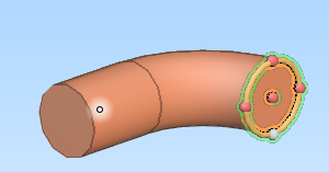
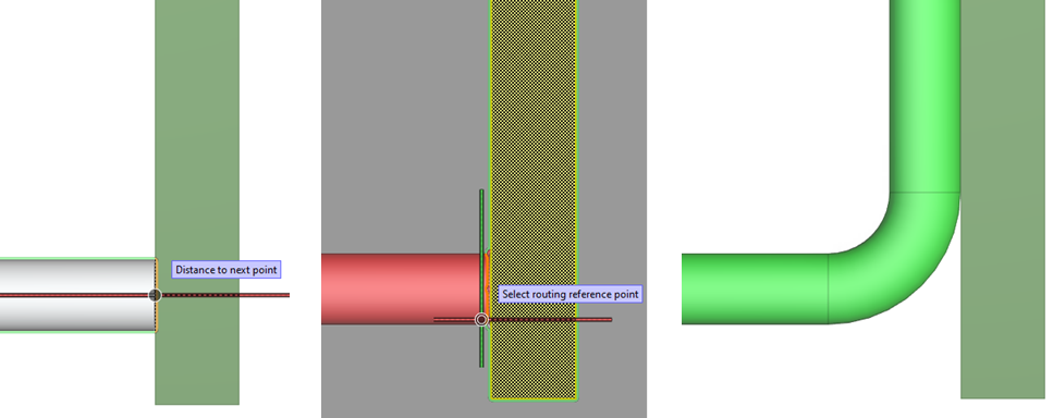
Allows selecting one of the four quadrant points of the pipe as the reference point. This makes some of the other routing commands unavailable. After routing one straight piping part, the reference point is automatically returned to the centerline of the pipe.
Selecting a quadrant point as the reference point and using a selection plane that is perpendicular to the previous straight piping part forces an angle of at least 90 degrees, if possible. In the example below, a pipe is first routed to a wall, the reference point is changed to the side of the pipe, and then routing continues along the surface of the wall.
|
|
|
|
When enabled, the pipe being routed is aligned with the nearest main axis, if the deviation is within the tolerance value defined in the settings. See Tolerances. |
|
|
Opens a dialog for setting the radius value of free-radius bends. The given value is used until the user runs the command again and changes the value. |
||
|
Alt+M |
Starts the measuring tool Distance between points (Alt+M). |
|
|
Shift+B |
When enabled, the distance values in the on-screen tool and in the status bar show the length of the straight piping part that is currently being routed in a locked direction. When disabled (default):
|
|
|
|
See Show routing hints. |
|
|
|
||
|
|
When enabled, the routing tool uses data provided by CADMATIC P&ID to show where the pipe should be connected next, as described in P&ID integration in 3D routing. |
|
|
|
||
|
|
When enabled, if an asymmetric curve is placed automatically, it connects to the preceding piping part using its second connection point instead of the first one. See DM_GT_ASYMCURVE (11). |
|
|
|
Opens a menu for changing the digitization of 3D model objects. |
|
|
|
Opens a menu for navigating in the model. |
|
|
|
Opens a menu for managing point clouds. |
|
|
Undo |
U |
Undoes the last action. |
|
Done |
Enter |
Completes the pipe. |
|
Help |
H |
Opens the help topic Route. |
|
Cancel |
Esc |
Cancels the pipe routing. |