Branches
Default branch & functional description
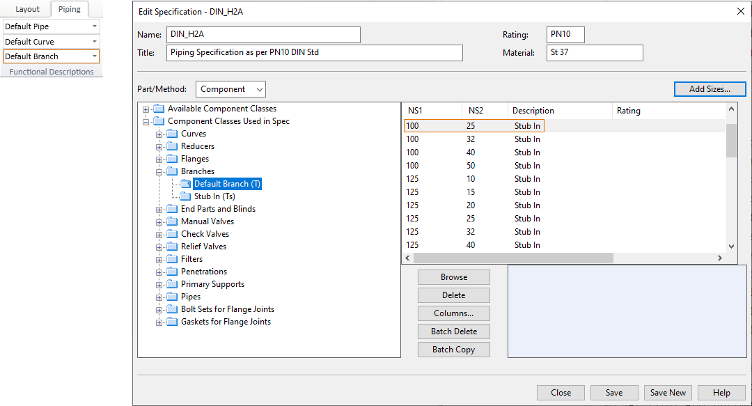
The default branch type is set in the piping specification—see Piping specifications.
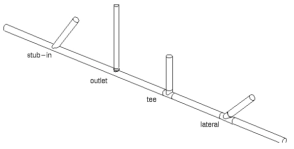
There are three branching methods:
-
Stub-in – The new pipe begins or ends as a straight pipe that intersects with the main pipe.
-
Outlet – An outlet component is placed on the surface of the main component. For example, an instrument nipple is often inserted as an outlet, as described in Insert an instrument nipple as outlet.
-
Branch component – This means branch components such as T-pieces, X-pieces, and laterals. The main pipe has to be a straight pipe. The pipe is cut and the branch component is inserted into the cut. The branch component is a Standard Component and belongs to the same pipeline as the main pipe.
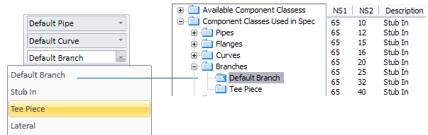
In this example, the default branch type is set to use 'Stub In' parts, and if the user wants to use T-pieces instead, before starting to route a new pipe the user changes the functional description from Functional descriptions in the Plant Modeller ribbon to 'Tee Piece':
Note: If the main pipe and the branch pipe belong to the same pipeline, the outlet component becomes part of the branch pipe. But, if they belong to different pipelines, then the outlet component is assigned to the main pipe.
Branch anchor node
When creating a branch to a piping part or inserting an onto line part, Plant Modeller creates a branch anchor node with the connection face type defined for branches in the catalog part used by the piping part.
The subtype of branch anchor nodes can be defined in Catalog Part Editor > Connection Faces > Branch in the middle of part. Branch anchor nodes can be added to pipes, elbows, and concentric or eccentric reducers that use internal shapes.
Plant Modeller checks compatibility for branch anchor nodes that use a 'Branch in the middle of part' subtype greater than zero. Compatibility is verified, for example, when creating a branch using a piping part, inserting a standard component as an outlet, or inserting an onto line part. Compatibility is also checked when an object is reinstalled due to changes in the catalog part used by the object.
Subtype 0, Branch middle of part, is the system default and fully compatible with branch parts of all subtypes of the connection faces Auxiliary point, Butt joint, Branch point, and Plain pipe end without requiring a compatibility definition.
Branch
You can start routing the branch pipe out of the main pipe or you can route the branch pipe so that it ends at the main pipe.
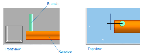
Routing branch pipe from main pipe
Prerequisites
-
The main pipe is checked out to you.
Do the following:
-
On the Piping tab, select Route > Route Pipe.
-
Move the cursor to the start point of the branch pipe inside the main pipe. You can use Shift+C to lock the cursor to centerline of the main pipe.
-
You can change the branch type if needed, as described in Changing the branch type in routing.
-
Right-click the work view and select Create branch > Branch.
-
Press Enter to accept the main pipe.
-
Select the system, pipeline, specification, and nominal size. The default values are the values of the main pipe. Then click OK.
-
Define the direction of the branch.
-
Route the pipe as required, and then press Enter to complete it.
Routing branch pipe to main pipe
Prerequisites
-
The main pipe is checked out to you.
Do the following:
-
On the Piping tab, select Route > Route Pipe and route the branch pipe as required.
-
Move the cursor to the intended branch location inside the main pipe.
-
Right-click the work view and select Create branch > Branch.
-
Press Enter to accept the main pipe.
-
Press Enter to accept the branch pipe.
Branch with component
In the piping context menu, select Create branch > Branch with component to create the start of a branch with a component (cylinder, cone, eccentric cone, or curve) which is cut by the main pipe. The curve can also be a bend. Branches are also allowed in cones and curves (for example, an outlet into a reducer).

Eccentric branch
You can connect a branch pipe also so that the centerlines of the main pipe and the branch pipe do not intersect. To do this, the branch pipe must be smaller than the main pipe and it has to fit totally in the main pipe.
-
Define the branch starting point as close to the point where the centerline of the branch pipe intersects the surface of the main pipe as possible, and select Create branch > Eccentric branch from the context menu.
Eccentric branch with component
In the piping context menu, select Create branch > Eccentric branch to create an eccentric branch with a component.
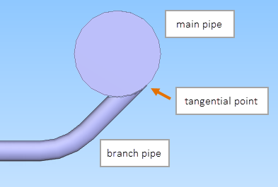
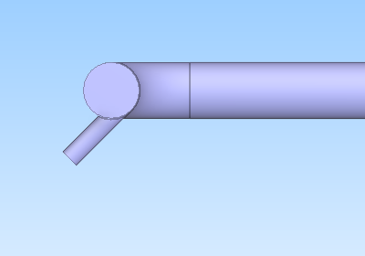
Tangential branch
You can insert a branch pipe as a tangent to the main pipe.
Routing tangential branch from main pipe
You can start routing a tangential branch from a main pipe.
Prerequisites
-
The piping specification of the main pipe defines a stub-in method for the required branch type/size.
 Show/hide example
Main pipe is 100 mm, you want to insert a tangential branch pipe that is 25 mm, and pipe routing uses "Default Branch" for branches. Therefore, the piping specification must allow Default Branch where NS1 is 100, NS2 is 25, and method is "Stub in".
-
The main pipe is checked out to you.
Do the following:
-
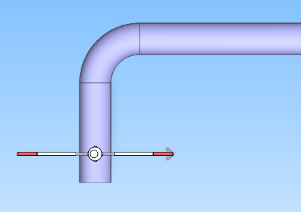
Select Piping tab > Pipe group > Route > Route pipe.
-
Set the view direction of the work view so that you are looking at the main pipe directly from the top.
-
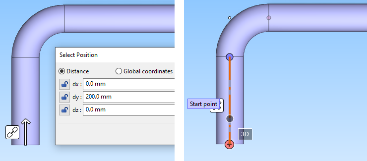
Navigate to the intended position of the branch pipe along the length of the main pipe.
Tip: You can, for example, press Q to move to the connection at the end of the main pipe and then press D to define the distance to the tangential point.
-
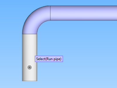
Right-click the work view and select Create branch > Tangential branch from the context menu.
The main pipe is selected and highlighted. If a wrong pipe was selected, press Space to select the next nearest pipe.
-
Press Enter to accept the main pipe.
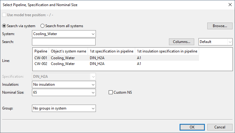
The Select Pipeline, Specification and Nominal Size dialog opens.
-
Define the system and the other properties of the branch pipe, and click OK.
The selection wheel is displayed.
-
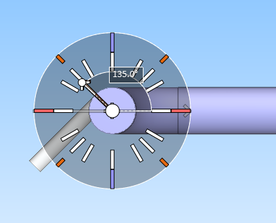
Change the view direction so that you are looking toward the end of the pipe and the selection wheel.
-
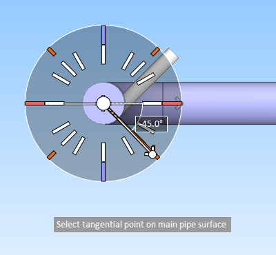
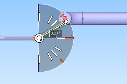
Use the selection wheel or the Enter angle (I) command to define the tangential point on the surface of the main pipe, and click to accept the tangential point.
Note: After accepting the tangential point, you can still return to the selection wheel with the Change tangential point (P) command, if needed.
-
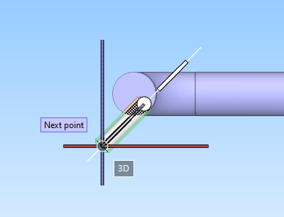
Start routing the branch pipe from the tangential point to the required direction.
-
After picking at least one routing point, you can press Enter to complete the branch pipe.
Routing tangential branch to main pipe
You can end the routing of a branch pipe by inserting it as a tangent to a main pipe.
Prerequisites
-
The piping specification of the main pipe defines a stub-in method for the required branch type/size.
Show/hide example
Main pipe is 100 mm, you want to insert a tangential branch pipe that is 25 mm, and pipe routing uses "Default Branch" for branches. Therefore, the piping specification must allow Default Branch where NS1 is 100, NS2 is 25, and method is "Stub in".
-
The main pipe is checked out to you.
Do the following:
-
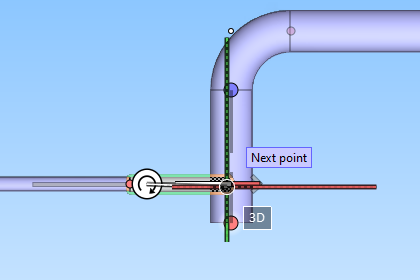
Route the branch pipe normally, until you are ready to insert the end of the branch into the main pipe. Make sure the routing direction is not locked, so that the program can set the branch pipe to the required angle.
-
Change the view direction so that you are looking at the main pipe directly from the top.
-
Right-click the work view and select Create branch > Tangential branch from the context menu.
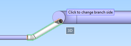
The main pipe is selected and highlighted, and the branch pipe is inserted into the main pipe. If the tangential point is initially on the wrong side of the main pipe, click to move the branch to the opposite side.
Then press Enter to accept the tangential point.
-
Press Enter to complete the branch pipe.
Outlet component geometry types
If the main component is a straight pipe, the outlet component can be of type DM_GT_2P, DM_GT_FIXCURVE, or DM_GT_ASYMCURVE.
If the main component is not a straight pipe, the outlet component must be of type DM_GT_2P.
For information on geometry types, see Geometry types.
Points and directions
If the main component is a straight pipe, the reference point of the branch is located at the intersection point of the centerlines.
If the main component is a curve, the reference point of the branch is located at the curve point nearest to the defined point. In this case, the centerline of the branch pipe is forced to go through the reference point.
If the branch component is a T-piece or X-piece, the branch direction is forced to be perpendicular to the centerline of the main component.
If the branch component is a lateral, the angle between the branch direction and the centerline of the main component is set according to the angle specified in the Dimension Table of the lateral. The plane where the centerline of the branch pipe is placed is determined by the direction vector defined by the user and the centerline of the main component. Thus, the user-specified direction determines the rotation of the branch component around the centerline of the main component.
For T-pieces and laterals connection point 4, and for X-pieces connection point 5, is located at the intersection of the centerlines. The next routing point is located at connection point 3. If the branch is to be made as a stub-in, then the program computes the intersection point of the surface of the main component and the branch direction. This intersection point is the next routing point.
If the branch is made using an outlet component, then the angle between the main pipe and the branch pipe can be "fixed" by specifying an extra angle quantity in the Dimension Table of the outlet component. In this case, the geometry is defined in the same way as for T-pieces. The program computes the intersection point of the surface of the main component and the branch direction. Connection point 1 of the outlet component is located at that intersection point. If the geometry type of the outlet component is not DM_GT_2P, then the program requests an additional direction to determine the orientation of the outlet. This is typically needed for bending branches. If the geometry type of the component is DM_GT_2P and its component model is defined using GDL, the secondary direction of connection point 1 is oriented so that it is perpendicular to the plane defined by the centerlines. The next routing point is located at connection point 3 or 2 of the outlet component.