Edit
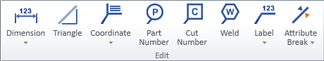
On the Home tab of the isometric view editor, the Edit group contains the following tools.
Dimension

You can annotate isometric drawings with important dimensions such as lengths, distances, and angles.
You can insert, modify, and delete dimensions with the tools in the Dimension menu. You can also modify and delete dimensions with the generic tools described in Modify.
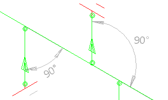
Dimension | Angular dimension for branch
Dimension
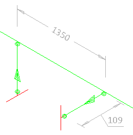
You can show various dimensions by selecting two geometry points from the isometric drawing. The direction of the dimension line can be either axial (aligned with a main axis) or non-axial (aligned with the vector between the dimensioned points). The dimension text can be at the center of the dimension line, at a user-defined position along the dimension line, or at the end of a leader line. A reference line is automatically added to each side of the dimension line.
Prerequisites
-
Project administrator can define the properties and the colors of dimensions in Annotation settings.
Do the following:
-
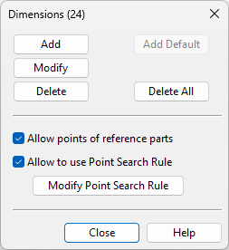
In the Edit group, select Dimension > Dimension. The Dimensions dialog opens. The title row shows the number of existing dimensions in parentheses.
-
You can add dimensions.
-
To generate all possible dimensions with default settings, click Add Default. This is only available when the drawing has no dimensions.
-
To add dimensions manually, do the following:
 Show/hide details
First, define which geometry points to use. For complex geometries, it is easier to add dimensions if you filter out unnecessary point types.
-
Allow points of reference parts – This option allows a dimension to start from or end at a reference part point. Clear the option to exclude these points.
-
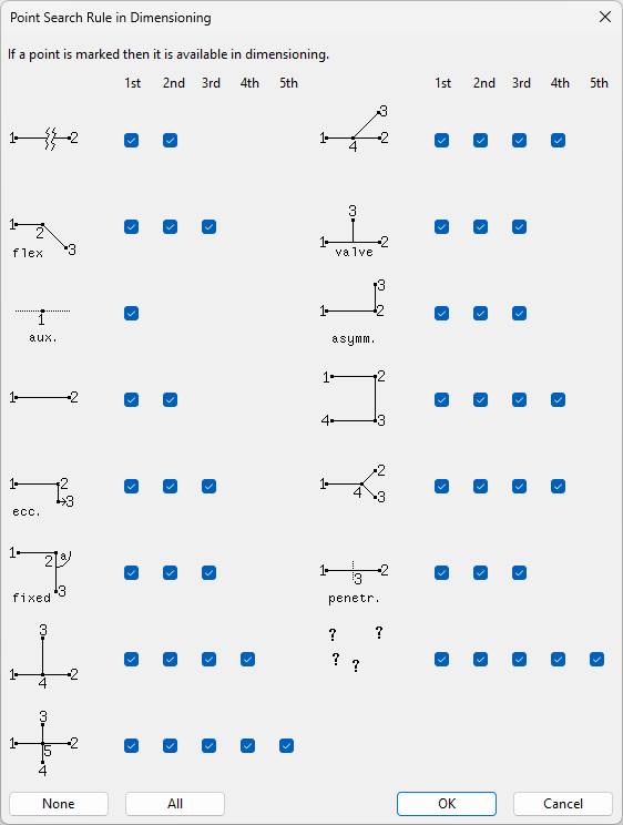
Allow to use Point Search Rule – This option allows you to define which points you can select as the start or end point of a dimension. Select the option and click Modify Point Search Rule to open a dialog where these settings can be defined.
Then, add the dimensions:
-
Click Add.
-
Pick the start and end points.
-
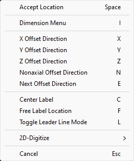
You can change the direction of the dimension line or the position of the dimension text with context-menu commands.
-
Accept location (Space)
-
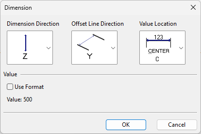
Show dimension menu (I) – Opens the Dimension dialog, where you can change the direction of dimension lines and reference lines, the location of the dimension text, and the content of the dimension text. In the dimension text format string, the default dimension value is indicated by %s.
-
Next dimension direction (E) – Selects the next offset direction: X, Y, or Z.
-
X direction (X)
-
Y direction (Y)
-
Z direction (Z)
-
Nonaxial direction (N)
-
Center label (C) – Sets the dimension value to the middle of the dimension line.
-
Free label location (F) – Allows the dimension value to be positioned anywhere within the dimension line.
-
Leader line (L) – Select whether to show the dimension value within the dimension line or at the end of a leader line.
-
-
Move the dimension line and click to confirm its location.
-
Pick the next dimension's start point or press Esc to finish.
-
-
-
You can modify dimensions.
-
To move individual dimensions or edit them with context-menu commands, click Modify, then click the dimension to modify. When ready, press Esc to finish and return to the dialog.
-
-
You can delete dimensions.
-
To delete individual dimensions, click Delete, then click each dimension to remove. When ready, press Esc to finish and return to the dialog.
-
To delete all dimensions, click Delete All. You are prompted to confirm the action.
-
-
Click Close.
Angular dimension for branch
You can add markings that show the angle between a main pipe and a branch pipe.
Prerequisites
-
Project administrator can define the properties and the colors of dimensions in Annotation settings.
Do the following:
-
In the Edit group, select Dimension > Angular dimension for branch.
-
Click a branch part. The angular dimension is shown in the drawing and you are prompted to confirm the action.
-
Press Esc to finish.
Triangle

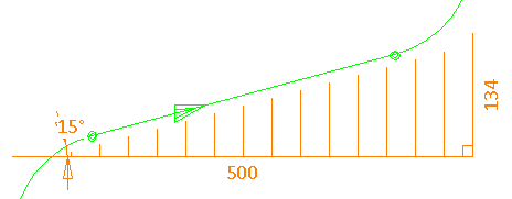
You can add a right triangle to show that pipeline is not aligned with the main coordinate axes. The triangle marking can show the legs of the triangle, the dimensions of the legs, and the angle of the pipe. The triangle can be placed on either side of the pipe.
Prerequisites
-
Project administrator can define the properties and the colors of triangles in Annotation settings.
Do the following:
-
In the Edit group, click Triangle. The Triangles dialog opens. The title row shows the number of existing triangle markings in parentheses.
-
You can add triangles.
-
To generate all possible triangles with default settings, click Add Default. This is only available when the drawing has no triangles.
-
To add triangles manually, do the following:
Show/hide details
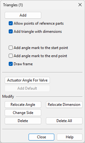
First, define which geometry points to use and what markings to include in the triangles.
-
Allow points of reference parts – This option allows a triangle to start from or end at a reference part point. Clear the option to exclude these points.
-
Add triangle with dimensions – This option dimensions the legs of the triangle. Clear the option to not dimension the legs.
-
Add angle mark to the start point – This option shows the angle value at the start point of the triangle. Clear the option to not show the angle.
-
Add angle mark to the end point – This option shows the angle value at the end point of the triangle. Clear the option to not show the angle.
-
Draw frame – This option draws the legs of the triangle. Clear the option to not show them.
Then, add the triangles.
-
Click Add.
-
Pick the start and end points.
-
Depending on the settings, you might be prompted to position the angle values and leg dimensions.
-
-
To add labels that show the angle of the actuator in a valve (DM_GT_VALVE), click Actuator Angle For Valve, and click each valve to label. When ready, press Esc to finish and return to the dialog.
-
-
You can modify triangles.
-
To move the angle labels of a triangle, click Relocate Angle, click the triangle, then move each angle value and click to confirm its new location. When ready, press Esc to finish and return to the dialog.
-
To move the dimension texts of a triangle, click Relocate Dimension, click the triangle, then move each dimension text and click to confirm its new location. When ready, press Esc to finish and return to the dialog.
-
To move triangles to the other side of the pipe, click Change Side, and click each triangle to change. When ready, press Esc to finish and return to the dialog.
-
-
You can delete triangles.
-
To delete individual triangles, click Delete, then click each triangle to remove. When ready, press Esc to finish and return to the dialog.
-
To delete all triangles, click Delete All. You are prompted to confirm the action.
-
-
Click Close.
Coordinate

Coordinate
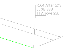
You can insert labels that show the coordinates of a geometry point.
Prerequisites
-
Project administrator can define the color of coordinate labels in Annotation settings.
Do the following:
-
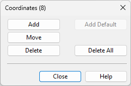
In the Edit group, select Coordinate > Coordinate. The Coordinates dialog opens. The title row shows the number of existing coordinate labels in parentheses.
-
You can add coordinate labels.
-
To generate all possible coordinate labels with default settings, click Add Default. This is only available when the drawing has no coordinate labels.
-
To add coordinate labels manually, click Add, click a geometry point to label, move the label and click to confirm its location. When ready, press Esc to finish and return to the dialog.
-
-
You can modify coordinate labels.
-
To move individual coordinate labels, click Move, click a label, move the label and click to confirm its new location. When ready, press Esc to finish and return to the dialog.
-
-
You can delete coordinate labels.
-
To delete individual coordinate labels, click Delete, then click each label to remove. When ready, press Esc to finish and return to the dialog.
-
To delete all coordinate labels, click Delete All. You are prompted to confirm the action.
-
-
Click Close.
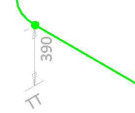
Line coordinate
You can insert labels that show the distance of a geometry point from a coordinate axis.
Prerequisites
-
Project administrator can define the color of coordinate labels in Annotation settings.
Do the following:
-
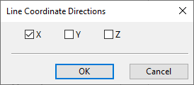
In the Edit group, select Coordinate > Line coordinate. The Line Coordinate Directions dialog opens.
-
Select which coordinate axis or axes to use, and click OK.
-
Click a geometry point in the drawing, and then click the location where to place the label.
(If you selected to use more than one coordinate axis, place a label for each additional axis in the same way.)
-
Press Esc to finish.
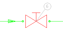
Part Number

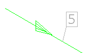
You can insert part number labels.
Prerequisites
-
Project administrator can define the color of part numbers in Annotation settings.
Do the following:
-
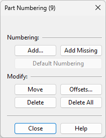
In the Edit group, click Part Number. The Part Numbering dialog opens. The title row shows the number of existing part number labels in parentheses.
-
You can add part numbers.
-
To generate all possible part number labels, click Default Numbering. This is only available when the drawing has no part number labels.
-
To generate the missing part number labels in a drawing that already contains labels, click Add Missing.
-
To add part numbers manually, do the following:
Show/hide details
-
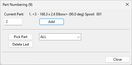
Click Add. The Part Numbering dialog opens. The title row shows the number of existing part number labels in parentheses.
-
Use the Pick Part tool to select the part from the drawing. If you first select a geometry type from the drop-down menu, the pick tool filters out all other geometry types.
-
Current Part shows the selected part and the part number. Edit the part number, if needed.
-
Click Add.
-
Move the label and click to confirm its location.
-
Add another part number in the same way or click Close to close the dialog.
-
-
-
You can modify part number labels.
-
To move individual part number labels, click Move, then move a label and click to confirm its new location. Press Esc to finish and return to the dialog.
-
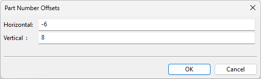
To move all part number labels by specified horizontal and vertical offsets, click Offsets, enter the offset values, then click OK.
-
-
You can delete part number labels.
-
To delete individual part number labels, click Delete, then click each label to remove. Press Esc to finish and return to the dialog.
-
To delete all part number labels, click Delete All. You are prompted to confirm the action.
-
-
Click Close.
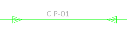
Cut Number

You can insert cut number labels.
Prerequisites
-
Project administrator can define the color of cut numbers in Annotation settings.
Do the following:
-
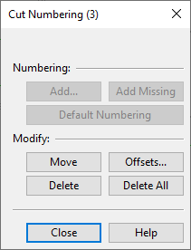
In the Edit group, click Cut Numbering. The Cut Numbering dialog opens. The title row shows the number of existing cut number labels in parentheses.
-
You can add cut number labels.
-
To generate all possible cut number labels with default settings, click Default Numbering. This is only available when the drawing has no cut number labels.
-
To generate the missing cut number labels in a drawing that already contains labels, click Add Missing.
-
To add cut number labels manually, do the following:
Show/hide details
-
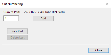
Click Add. The Cut Numbering dialog opens.
-
Use the Pick Part function to select the target part from the drawing. If you first select a geometry type from the drop-down menu, the pick tool filters out all other geometry types.
-
In the Current Part field, type the cut number to be shown in the label.
-
Click Add.
-
Click the location where to place the label.
-
Add another cut number in the same way or click Close to close the dialog.
-
-
-
You can modify cut number labels.
-
To move individual cut number labels, click Move, click a label, move the label and click to confirm its new location. When ready, press Esc to finish and return to the dialog.
-
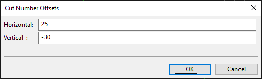
To move all cut number labels by specified horizontal and vertical offsets, click Offsets, enter the offset values, and click OK.
-
-
You can delete cut number labels.
-
To delete individual cut number labels, click Delete, then click each label to remove. Press Esc to finish and return to the dialog.
-
To delete all cut number labels, click Delete All. You are prompted to confirm the action.
-
-
Click Close.
Weld

You can insert labels that indicate where weld points are located.
Prerequisites
-
Project administrator can define the labeling settings in Weld/joint labels.
Do the following:
-
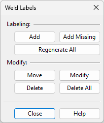
In the Edit group, click Weld. The Weld Labels dialog opens.
-
You can add weld labels.
-
To generate labels to all weld points, click Regenerate All. This function deletes any existing labels and creates new labels with consecutive index numbers.
-
To generate the missing weld labels in a drawing that already contains labels, click Add Missing. This function always assigns a new index number to the label, it does not re-use previously used numbers that are now free.
-
To add weld labels manually, do the following:
Show/hide details
-
Click Add.
-
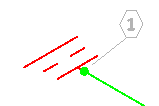
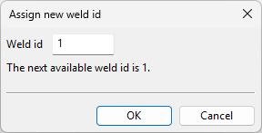
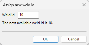
Pick a weld point from the drawing. The Assign new weld id dialog opens, displaying the next free weld ID.
-
Enter a new weld ID if needed, and click OK.
-
Move the label and click to confirm its location.
-
Pick the next weld point to label or press Esc to finish and return to the dialog.
-
-
-
You can modify weld labels.
-
To move individual weld labels, click Move, click a label, move the label and click to confirm its new location. When ready, press Esc to finish and return to the dialog.
-
To change the weld number of individual weld labels, click Modify, then click the label to modify. You are prompted to either accept the next available ID or enter a new one.
When ready, press Esc to finish and return to the dialog.
Note: The Modify button is not available if the project administrator has enabled the Create weld IDs… option in Isometric Groups.
-
-
You can delete weld labels.
-
To delete individual weld labels, click Delete, then click each label to remove. When ready, press Esc to finish and return to the dialog.
-
To delete all weld labels, click Delete All. You are prompted to confirm the action.
-
-
Click Close.
Label

Insert label | Free text | Valve operator | Valve position | Pipeline | Slope | Height mark | NS change | Branch offset | Extra length | Area clear
Insert label
You can add labels that use a label definition from the database. Label definitions can use data requests to show information about the referenced objects.
Prerequisites
-
In the library or the project database, project administrator has created a suitable "pi" label definition and set it to be shown in the label menu. See Label Definitions.
Do the following:
-
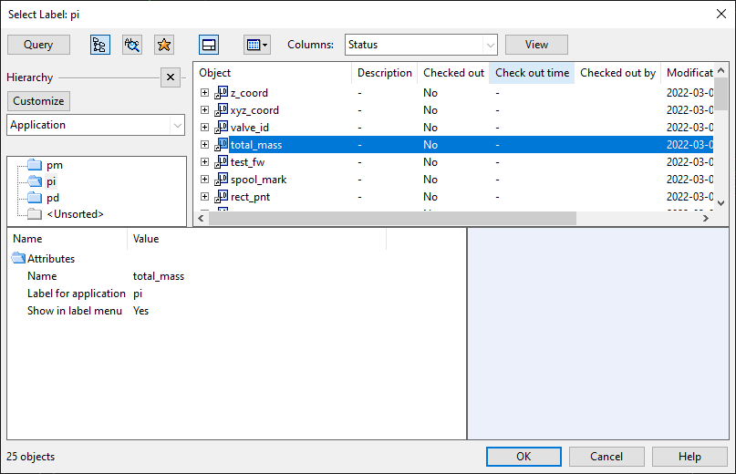
In the Edit group, select Label > Insert label. The Select Label object browser dialog opens.
-
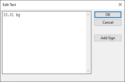
In the "pi" application hierarchy, select the label definition to use and click OK. The Edit Text dialog opens, displaying the default text provided by the label.
-
You can edit the text as required. Click Add Sign to add one of the following symbols to the text:
-
Degree sign: °
-
Plus-minus sign: ±
-
Diameter sign: ø
-
-
Click OK.
-
Move the label to the intended location and click to accept.
-
You can add another label of the same type or click Cancel.
-
You can select a different label type or click Cancel to exit the tool.
Free text
You can add labels that show a text string. The label can be attached to a part or a geometry point with a reference line, and the label text can be framed with a box or diamond shaped border.

Prerequisites
-
Project administrator has defined text color in Annotation settings.
Do the following:
-
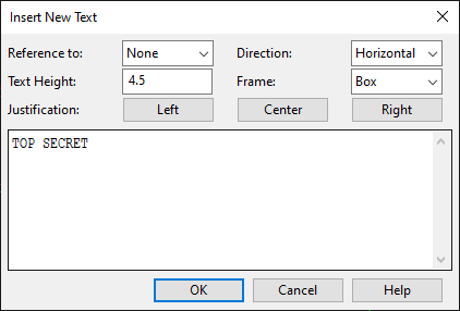
In the Edit group, select Label > Free text. The Insert New Text dialog opens.
-
In the text pane, enter the text to be shown in the label. Text labels have these limitations:
-
158 characters in one row.
-
999 characters in one label.
-
-
Define the text properties:
-
Reference to – Select whether the label should have a reference line: None, Part, Point.
-
Text Height – Specify the text height as a value between 0.1 and 25.
-
Direction – Select the text direction: Horizontal, Vertical, X-axis, Y-axis, Z-axis.
-
Frame – Select whether to draw a border around the label text: None, Box, Diamond.
-
-
Select text alignment by clicking Left, Center or Right.
-
Click OK.
-
Move the label to the intended location and click to accept. The Insert New Text dialog re-opens.
-
You can add another text label or click Cancel to exit the tool.
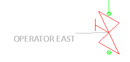
Valve operator
You can add labels that show on which side of the valve the operator is.
Do the following:
-
In the Edit group, select Label > Valve operator.
-
Click a valve.
-
Move the cursor to where you want to place the label and click to accept the location.
-
Continue inserting valve labels or press Esc to finish.
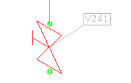
Valve position
You can add labels that show the Valve Position ID attribute ("vpo") of a valve.
Do the following:
-
In the Edit group, select Label > Valve position.
-
Click a valve.
-
Move the cursor to where you want to place the label and click to accept the location.
-
Continue inserting valve labels or press Esc to finish.
Pipeline
You can add labels that show the name of the pipeline.
Do the following:
-
In the Edit group, select Label > Pipeline.
-
Click a pipe.
-
Move the cursor to where you want to place the label and click to accept the location.
-
Continue inserting pipe labels or press Esc to finish.
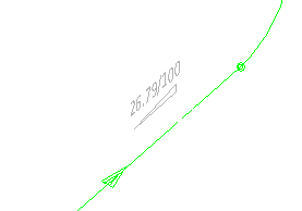
Slope
You can add labels that show the angle of sloped pipes.
Do the following:
-
In the Edit group, select Label > Slope.
-
Click a sloped pipe.
-
Move the cursor to where you want to place the label and click to accept the location.
-
Continue inserting slope labels or press Esc to finish.
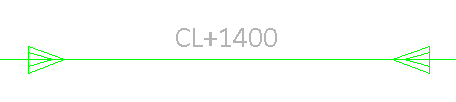
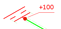
Height mark
You can add labels that show the elevation of horizontal straight pipes in the format "CL+<value>".
Do the following:
-
In the Edit group, select Label > Height mark.
-
Click a straight, horizontal pipe.
-
Move the cursor to where you want to place the label and click to accept the location.
-
Click another straight, horizontal pipe or press Esc to finish.
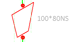
NS change
You can add labels to reducers and stub-in branches to denote the change from one nominal size to another. The tool will prompt you if such labels already exist in the active drawing—if you continue, the existing labels are not automatically removed, potentially resulting in duplicates.
Do the following:
-
In the Edit group, select Label > NS change. The label for the first stub-in or reducer is displayed.
-
Move the cursor to where you want to place the label and click to accept the location.
-
Continue until all NS change labels have been inserted.
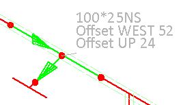
Branch offset
You can add labels that show the offset of stub-in branches that do not intersect with the pipe centerline.
Do the following:
-
In the Edit group, select Label > Branch offset. The label for the first branch is displayed.
-
Move the cursor to where you want to place the label and click to accept the location.
-
Continue until all branch offset labels have been inserted.
Extra length
You can add labels that show the extra length added to straight pipes via the Isometric Groups context menu.
Do the following:
-
In the Edit group, select Label > Extra length. The label for the first extra length location is displayed.
-
Move the cursor to where you want to place the label and click to accept the location.
-
Continue until all extra length labels have been inserted.
Area clear
You can add blank labels that hide the contents of a rectangular area in the active drawing. The color of this area is the same as the drawing background color.
Do the following:
-
In the Edit group, select Label > Area clear.
-
In the Give the width and the height for the area clear label dialog, enter the width and height of the label, and click OK.
-
Move the cursor to where you want to place the label and click to accept the location.
-
Continue inserting area clear labels of the same size or press Esc to finish.
Attribute Break

You can add attribute break labels to locations where the value of a specific attribute (tag) changes in the isometric drawing. You can use this, for example, to point out changes in specification.
Specification <spc> | Insulation <ins> | Spool <spn> | User defined attribute
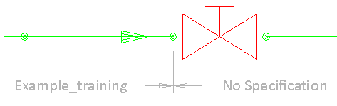
Specification <spc>
You can add an attribute break label to each location where the specification changes.
Do the following:
-
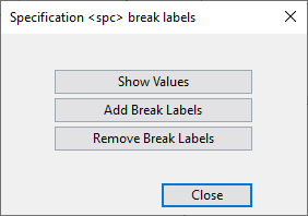
In the Edit group, select Attribute Break > Specification <spc>. The Specification <spc> break labels dialog opens.
-
Click Remove Break Labels if you want to remove all existing attribute break labels that use this tag.
-
Click Show Values if you want to check which values the "spc" tag has in this isometric drawing.
Tip: To add labels, there must be at least two different values for this tag.
-
Click Add Break Labels to add a label to each location where the value of the "spc" tag changes.
-
Click Close.
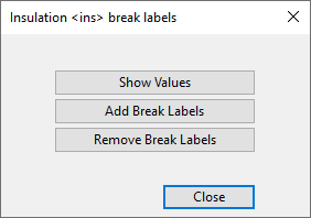
Insulation <ins>
You can add an attribute break label to each location where the insulation material changes.
Do the following:
-
In the Edit group, select Attribute Break > Insulation <ins>. The Insulation <ins> break labels dialog opens.
-
Click Remove Break Labels if you want to remove all existing attribute break labels that use this tag.
-
Click Show Values if you want to check which values the "ins" tag has in this isometric drawing.
Tip: To add labels, there must be at least two different values for this tag.
-
Click Add Break Labels to add a label to each location where the value of the "ins" tag changes.
-
Click Close.
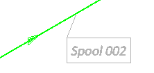
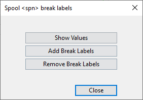
Spool <spn>
You can add an attribute break label to each location where the previous spool ends and a new spool begins.
Do the following:
-
In the Edit group, select Attribute Break > Spool <spn>. The Spool <spn> break labels dialog opens.
-
Click Remove Break Labels if you want to remove all existing attribute break labels that use this tag.
-
Click Show Values if you want to check which values the "spn" tag has in this isometric drawing.
Tip: To add labels, there must be at least two different values for this tag.
-
Click Add Break Labels to add a label to each location where the value of the "spn" tag changes.
-
Click Close.
User defined attribute
You can add an attribute break label to each location where the value of a specific attribute changes.
Do the following:
-
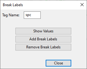
In the Edit group, select Attribute Break > User defined attribute. The Break Labels dialog opens.
-
In the Tag Name field, enter the tag of the attribute you want to use.
-
Click Remove Break Labels if you want to remove all existing attribute break labels that use this tag.
-
Click Show Values if you want to check which values the tag has in this isometric drawing.
Tip: To add labels, there must be at least two different values for this tag.
-
Click Add Break Labels to add a label to each location where the value of the tag changes.
-
Click Close.