Isometric panes
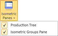
On the Piping isometric tab, the Isometric panes menu allows showing or hiding panes that relate to managing isometric groups and isometric documents.
Production Tree pane
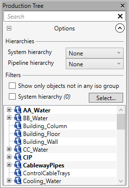
On the Piping isometric tab, Isometric panes > Production Tree shows or hides the Production Tree pane that allows you to browse the hierarchical object structure of the area model and manage how piping parts are assigned to isometric groups.
Opening the production tree pane docks the pane to the left side of the application window. You can drag the pane by its title bar to detach the pane from its current position and then either dock the pane to another part of the window or let the pane float anywhere on the screen, as appropriate. For general information on managing panes in Plant Modeller, see Panes.
You can use the search bar to quickly find specific items from the tree. The search works like the model tree search described in Searching the tree, except search prefixes are not supported here.
In the tree, different object types are indicated by type-specific icons. There are also icons that indicate whether entities are currently checked out to you or to another user. You can browse the tree, select items to see their properties in the Properties pane, and manage items with context-menu commands.
While the Model Tree pane shows the complete object hierarchy, the isometric production tree only lists objects that can be assigned to an isometric group. In the tree, branches whose name is in bold contain objects that are not assigned to an isometric group in the active isometric group type, and you can hide all the other branches by selecting the option Show only objects not in any iso group.
You can right-click an item in the list to use the commands in the context menu.
Production Tree context menu
The context menu of the Production Tree pane includes the following commands that you can use to manage how piping parts are assigned to isometric groups.
-
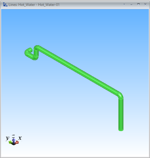
Show line preview – Opens a shaded view that shows the pipeline to which the selected object belongs.
-
Locate in model – Zooms to and highlights the entity in the active work view. Similarly, when you are in a work view, you can use a context-menu command to find out where the model object is located in the production tree.
-
Locate in isometric groups pane – Selects the entity in Isometric Groups Pane.
-
Fit filter box – Sets a filter box around the specified entities in the active (shaded) work view, so that only the objects that are inside the filter box are shown, and opens the Edit Filter Box dialog for adjusting the size of the filter box. For details, see Edit box (Shift+4).
-
Check out – Checks out the specified entities. On a replica server this also requests ownership, if needed. A green icon on the right indicates that the entity is currently checked out to you; a red icon indicates that the entity is checked out to another user.
-
Check in – Checks in the specified entities.
-
Relinquish ownership – Relinquishes the ownership of the selected, checked-in entities from the replica server to the master server.
-
Properties – Opens the Properties pane, showing object information, if applicable to the object type. For details, see Properties pane.
-
Reset weld IDs – Removes all existing weld IDs from selected pipelines and assigns new ones to all piping objects that are members of an isometric group and have welded connection faces. This ensures consecutive numbering throughout the pipeline and can be used when additions to the pipeline have caused irregular numbering.
Note: Using this command requires that the project administrator has enabled automatic assigning of weld IDs, as described in Isometric Groups.
-
-
Preview drawing – Performs automatic splitting of the selected pipelines, guided by the settings defined in Isometric Groups and Isometric Drawing. Following the split, it generates temporary isometric documents and opens the Export 2D Drawing dialog, enabling you to save the resultant drawing files to a designated folder. This functionality allows the production of preliminary drawings without the need to create any isometric groups or check out the model objects.
-
PCF – Opens a folder browser dialog for exporting the currently selected pipelines as PCF files into a designated folder, without having to create an isometric document or check out the model objects. This export uses predefined settings and requires a PCF export license.
For general information on the available export commands, see Export.
-
-
Create isometric group(s) of selected – Opens a dialog for creating one or more isometric groups for the selected objects. For details, see Create New Isometric Group.
-
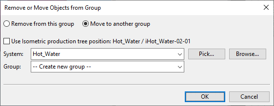
Remove from group – Select piping objects from the Production Tree pane and then this command to remove the objects from the current group or to assign them into another isometric group.
-
If the objects are in an isometric group, the Remove or Move Objects from Group dialog opens, and you can choose where to move the objects.
-
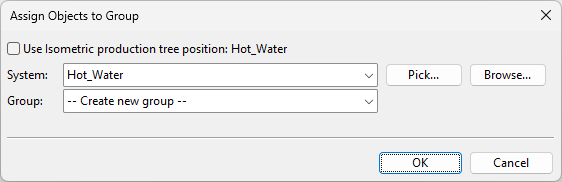
If the objects are not in an isometric group yet, the Assign Objects to Group dialog opens, and you can choose where to assign the objects. See also Assign.
-
-
Remove from group, pick from model – Select an isometric group from the Production Tree pane and then this command to remove objects from the group or to assign them into another group. You are prompted to select the objects from a shaded work view, and when you accept the set of objects, the Remove or Move Objects from Group dialog opens for choosing where to move the objects.
-
Delete isometric group – Deletes the selected isometric group.
Isometric Groups Pane
On the Piping isometric tab, Isometric panes > Isometric Groups Pane shows or hides the Isometric Groups pane that allows you to manage the existing isometric groups of the active isometric group type and create isometric drawings for them. Before you can create isometric documents, the project administrator must define the settings described in Isometric Drawing.
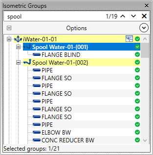
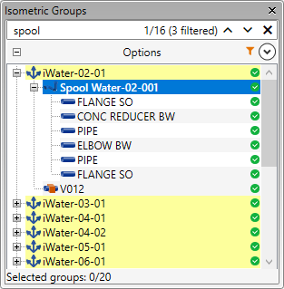
Isometric Groups search bar
In the Isometric Groups pane, you can search for a text string to locate a specific isometric group.
Do the following:
-
In the search bar, enter the text string you want to find. The search is not case-sensitive.
-
Press Enter to initiate the search. The search bar indicates the number of items that match the search, as well as those that match but are currently filtered out by Isometric Groups filters.
-
If there are fewer than 100 items to display, these items are highlighted in the tree and the first one is automatically selected.
-
If items matching the search cannot be displayed due to filtering, the search bar shows how many items are filtered out.
-
If no results appear, adjust the search string and try again.
-
-
Use the up/down arrows in the search bar to navigate between search results. Right-click an item to use the commands in the Isometric Groups context menu.
-
Click the X in the search bar to erase the search string and clear the search results.
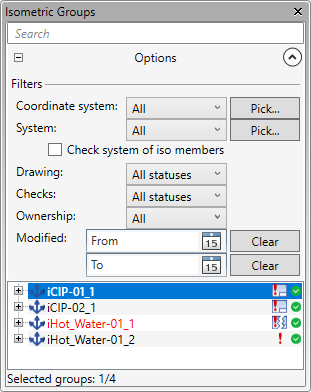
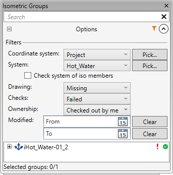
Isometric Groups filters
The Isometric Groups pane shows the isometric groups of the active isometric group type. You can use filtering to show only the isometric groups you are interested in. The orange filter icon ![]() indicates that the tree is filtered and does not show all the items. Also, searching the tree indicates if some of the search results are filtered out.
indicates that the tree is filtered and does not show all the items. Also, searching the tree indicates if some of the search results are filtered out.
Do the following:
-
In the Isometric Groups pane, open the Options section by clicking
 .
. -
Coordinate system – You can filter isometric groups by coordinate system, if the project contains local coordinate systems. For more information, see Coordinate Systems.
-
System – You can filter isometric groups by system. You can pick a system from a model object or select a filter from the drop-down menu:
-
All – Select this to show all existing groups regardless of their system.
-
[System] – Select a system to show only groups that belong to that system.
-
Production tree selection – Select this to show only groups whose system is currently selected in the Production Tree pane.
If you select the Check system of iso members option, then you also see isometric groups whose members belong to the system defined by the filter, even if the group itself belongs to some other system.
-
-
Status – You can filter the list based on the status of the associated isometric drawing. Select one of the following:
-
All statuses
-
OK
-
Missing
-
Broken geometry
-
-
Checks – You can filter the list based on the status of isometric checks. Select one of the following:
-
All statuses
-
OK
-
Failed
-
Outdated
-
-
Ownership – You can filter the list based on the availability of the isometric groups. Select one of the following:
-
All
-
Checked out by me
-
Available
-
Unavailable
-
-
Modified – You can filter the list to show only those isometric groups that have been modified within a specific period of time. You can define the time range by specifying the From date, the To date, or both From and To.
Tip: You can use the pane as your to–do list by setting To in the past, so that groups disappear as you modify them.
Isometric Groups list
The Isometric Groups pane lists the isometric groups of the active isometric group type. You can use Isometric Groups search bar and Isometric Groups filters to find a specific group.
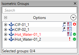
The name of the isometric group is followed by three columns of icons:
-
First column shows if the isometric group or its member contains field welds
 or extra lengths
  or both
  .
. -
Second column shows status information:
-
Isometric document is OK
 , contains broken geometry
  (isometric group has changed after the document was created), or is linked to Sister project management
  .
. -
Isometric checks have failed
 /
/  /
/  or they are out of date
  /
/  /
/  (isometric group has changed after the checks were run).
 -
No icon means that there is neither an isometric document nor failed/out-of-date checks.
-
-
Third column shows whether the isometric group or its member is checked out to you
 or owned by another COS server
  . No icon means that you can check out the group.
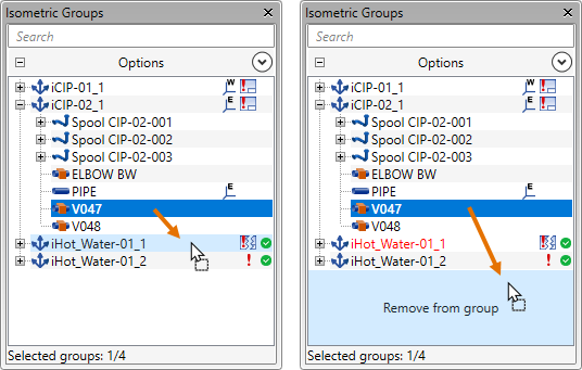
You can move items between isometric groups or remove items from isometric groups by dragging. If the source or the target group already has a document, you are prompted to confirm the action, as changing a group's contents causes the associated document to be "broken".
You can right-click an item in the list to use the commands in the context menu.
Isometric Groups context menu
The context menu of the Isometric Groups pane includes the following commands that you can use to manage the contents of isometric groups and preview, create, and update isometric documents.
-
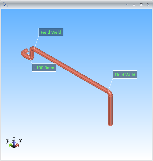
Show group preview – Opens a shaded view that shows the model objects of the isometric groups related to the current tree selection. If the isometric has field welds or extra lengths, they are shown in the preview. If you select an entity from the tree, the respective objects are highlighted in the preview.
-
Locate in model – Zooms to and highlights the entity in the active work view.
-
Locate in production tree – Selects the entity in Production Tree pane.
-
Check out – Checks out the isometric group and its members. On a replica server this also requests ownership, if needed.
Note: To check out isometric documents, use the respective command in the Isometric Drawings Pane.
-
Check in – Checks in the isometric group and its members.
Note: To check in isometric documents, use the respective command in the Isometric Drawings Pane.
-
Relinquish ownership – Relinquishes the ownership of the selected, checked-in entities from the replica server to the master server.
-
Rename isometric group – Opens a dialog for renaming the isometric group. This also renames the isometric document, if it exists.
-
Properties – Opens the Properties pane.
-
Field welds – Allows defining field welds in the isometric group.
-
Extra lengths – Allows defining extra lengths in the isometric group.
-
Define spools – Allows creating spools for the objects in the selected isometric groups.
-
If you selected one isometric group, this command opens the Define spools dialog for defining spools for the isometric group. See Define or browse spools.
-
If you selected several isometric groups, this command deletes all their existing spools and generates new ones. The new spools are numbered with running numbering along the pipeline, so that the first spool gets the highest spool number previously found in the pipeline plus one. After this, you must recreate existing isometric documents.
Note: This command is available if the project administrator has not selected the use of pipe spool drawings in the Pipe Spool Drawing settings.
-
-
Browse spools – Opens the Browse spools dialog for browsing the spools of the selected isometric groups. See Define or browse spools.
Note: This command is available if the project administrator has selected the use of pipe spool drawings in the Pipe Spool Drawing settings.
-
Add missing weld IDs – Adds weld IDs to welded connections that do not have a weld ID yet. (Updating or recreating a document does this automatically.)
Note: Using this command requires that the project administrator has enabled automatic assigning of weld IDs in the Isometric Groups settings.
-
Delete isometric group – Deletes the selected isometric groups and associated isometric documents.
-
Add set from model – Allows selecting a set of objects from the model and adds them to the selected isometric group.
-
Remove from group – Select piping objects from the Isometric Groups pane and then this command to remove the objects from the current group or to assign them into another group. The Remove or Move Objects from Group dialog opens, and you can choose where to move the objects.
-
Remove from group, pick from model – Select this command to remove objects from the selected isometric group or to assign them into another isometric group. You are prompted to select the objects from a shaded work view, and when you accept the set of objects, the Remove or Move Objects from Group dialog opens for choosing where to move the objects.
Tip: You can also change group contents by dragging items in the Production Tree and Isometric Groups panes.
-
Production checks – Runs production checks on the selected isometric groups and then opens the Isometric Check Results.
-
Compare with model – Compares the isometric drawing of the selected isometric group (only one group at a time) to the group's model objects. This operation publishes an eBrowser model and opens it in eBrowser.
For more information on how the comparison works, see Model comparison in eBrowser documentation.
-
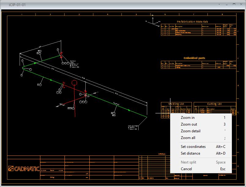
Preview isometric drawing – Shows a document preview for an isometric group that does not have a document yet. You can use the context-menu commands to zoom or to lock the cursor at a specific point.
-
Create/recreate isometric drawing – Creates a document for the selected isometric group. If the document already exists, the command updates the existing one by deleting and recreating the drawing views (publications, page annotations, and manually added pages are preserved).
-
Update isometric drawing – Updates the header information and the geometry of the isometric document while trying to preserve any manual modifications made in the document. Labels and property tags keep their locations, if the corresponding point or part still exists in the drawing, and manually set rotations for symbols are preserved.
Updating the drawing can be used, for example, to update component geometries that have been modified in the 3D model, or to update the values of inherited attributes that are printed on the drawing sheet. The command regenerates dimensions, part numbers, cut numbers, and weld numbers for all parts, and adds annotations defined in the Automatic Annotation settings to any new parts.
Isometric Drawings Pane
On the Piping isometric tab, Isometric panes > Isometric Drawings Pane shows or hides the Drawings pane that allows you to manage the existing drawings of the isometric groups currently selected in the Isometric Groups Pane.
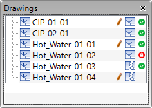
In the document list, icons indicate status as follows:
-
 – Document contains manual modifications.
 -
– Document is up-to-date.
-
– Document is broken: it does not contain the latest changes of the 3D model.
-
 – Document is checked out to this area.
 -
 – Document is checked out to another area. You cannot check it out.
 -
 – Document is linked to Sister project management or uses a different coordinate system. You cannot check it out.
Isometric Drawings context menu
The context menu of the Isometric Drawings Pane contains commands for managing isometric documents. Most of these commands are also available in the Manage tool.
-
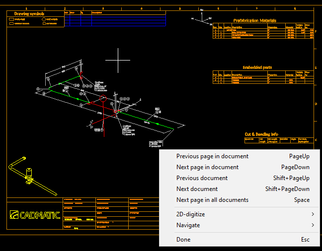
Show browsing view – Sequentially opens the selected isometric documents in browsing mode. Use the context-menu commands to navigate from one preselected document to another or to open the next available page. Press Esc to close the document viewer and return to the Drawings pane.
-
Check out – Checks out the selected isometric documents. On a replica server this also requests ownership, if needed.
-
Check in – Checks in the selected isometric documents.
-
Relinquish ownership – Relinquishes the ownership of the selected, checked-in isometric documents from the replica server to the master server.
-
Properties – Opens the COS Object Properties dialog, displaying information on the selected isometric document object.
-
Recreate – Updates the selected documents by deleting and recreating the drawing views (publications, page annotations, and manually added pages are preserved).
-
Update – Updates the geometry of an outdated isometric document while trying to preserve manual modifications. If the user has added new labels or added or moved property tags, they keep their location if the corresponding point/part still exists in the drawing. Also, manually set rotations for symbols are preserved. Dimensions, part numbers, cut numbers, and weld numbers are always regenerated for all parts, and new parts also get all the annotations that are defined in the Automatic Annotation settings.
-
Edit – Opens the selected isometric document in the Document editor.
-
Export – You can export the selected isometric documents. For general information on the available export commands, see Export.
-
Publish – Creates publications of the selected isometric documents. See Document publishing.
-
Delete – Deletes the selected isometric documents. You are prompted to confirm the action.