Inserting doubler plates
Perform the following to insert doubler plates to ends of beams and straight pipes. You can use shortcut keys or select commands from the context menu.
During insertion, you can press H to open this help topic. If you select a wrong object as the target, press Esc to cancel the selection.

Prerequisites
-
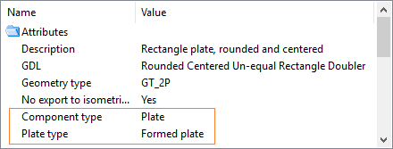
The catalog part to use for the doubler plate must have the attributes Component type = Plate and Plate type = Formed plate, and the related GDL object should define one parametric plate primitive. The system will extract the required boundary and thickness information from the plate primitive to determine the smallest plate that can be used to cover the end of the target object.

Note: It is recommended that you use samples from the CADMATIC example project when you create your own doubler plate parts.
Do the following:
-
In the Doubler Plate group of the Structural tab, click Add. The Doubler Tool Settings dialog opens.
-
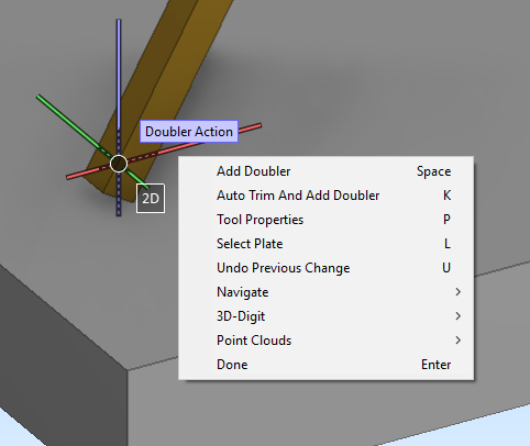
Specify the tool settings as described in Doubler tool settings, and click OK. The "Doubler Action" tooltip displays near the cursor to indicate that the doubler plate tool is enabled.
-
To insert a doubler plate that is aligned with the end of the target object, move the cursor over the target end and click the object or press Space (or select Add Doubler from the context menu), and then press Enter.
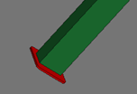
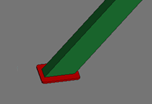
The plate is added and the target object is shortened accordingly if the settings specify so. If the target object belongs to a structural unit group, the doubler plate is added to the same group.

-
To auto-trim the target object and insert a doubler plate that is aligned with the trimmer object, move the cursor over the target end and press K (or select Auto Trim And Add Doubler from the context menu), and then press Enter.
If the system finds a potential trimmer object, it auto-trims the target object with a planar face obtained from the trimmer object, and then places a doubler plate between them. If the target object belongs to a structural unit group, the doubler plate is added to the same group.

-
You can undo insertions by pressing U (or select Undo Previous Change from the context menu). But, there is no redo command during insertion.
-
You can change the settings for the next insertion by pressing P (or select Tool Properties from the context menu).
-
You can change the plate part for the next insertion by pressing L (or select Select Plate from the context menu). The object browser opens, and you can select another part from the catalog.
Note: In this special context, the object browser's folders are filtered so that they only display catalog parts that are formed plates and thus valid to be used as doubler plates. Folders that do not contain valid doubler plate parts are displayed as empty. For more information on object browsers, see Object browser.
-
When there are no more doubler plates to add, press Esc.
After exiting the doubler plate tool, you can use the Undo/Redo buttons in the quick access toolbar to undo/redo the latest plate insertions.